 Until 2016, I had never purchased a commercial field antenna; I built all the ones I had ever used.
These days, I take a number of commercial antennas to the field and use them in my real-time videos and I really enjoy deploying and using them. My buddy Eric (WD8RIF) reminded me, though, that I hadn’t actually used a homebrew antenna in ages. He was right!
You see, while I believe commercial field antennas can be incredibly durable and compact, it’s important to note that antennas are one of the easiest components of an amateur radio system to build yourself. They require only the most simple of tools and are very affordable. And the best part? They can perform as well as those that are available commercially.
I also get a great deal of pleasure out of building things.
A simple goal
I’ve mentioned in previous posts that I often set a little goal that runs in the back of my mind for each park or summit activation I make.
On Monday, June 14, 2021, I made a simple goal: buy my antenna wire en route to Lake James State Park, build the antenna on site, and complete a valid Parks On The Air (POTA) activation.
A very simple antenna

I also decided to employ my Xiegu X5105 since 1.) it’s one of the most affordable general coverage QRP transceivers I own and 2.) it has a built-in antenna tuner (ATU).
One of the cool things about having an ATU is that, if it has the matching range, you can allow it to do the “heavy lifting” in terms of matching impedance.
Although I’d never put the X5105 to the test, I suspected its internal ATU would have the matching range to forgo building a 4:1 or 9:1 transformer and simply pair it directly with a random wire.
All I would need was a 28.5 foot length of wire for a radiator, at least a 17 foot length for a counterpoise, and a BNC to binding post adapter.
The antenna would benefit from multiple 17′ counterpoises, but I really wanted to keep this setup dead simple to prove that anyone can build an effective field antenna with a very minimum amount of components.
Even though I have plenty of wire lying around the house to build this simple antenna, I wanted to pretend I had none to prove that any wire would work.
And to add just a wee bit more challenge, I also limited myself to shopping for antenna wire between my home and the park without making a serious detour from my route. That really limited my options because there isn’t much in terms of commercial areas between me and Lake James State Park.
The wire
As I left the QTH, I decided that the best spot to shop was a Walmart in Marion, NC. It would only be a four minute round-trip detour at most. I had a hunch that Walmart would even have speaker wire which would be ideal for this application.
In my head, I imagined I would have at least three or four choices in speaker wire (various gauges and lengths), but turns out I had a difficult time finding some at Walmart. We live in such a Bluetooth world, I suppose there isn’t much demand for it these days. A store associate helped me find the only speaker wire they had which was basically a 100 foot roll of the “premium” stuff for $17 US.

While I would like to have paid a fraction of that, in the end it’s not a bad price because once you separate the two conductors, you have double the amount of wire: 200 feet.
Although the frugal guy in me cringed, I bit the bullet and purchased their speaker wire. To be clear, though, I could have found another source of wire in that Walmart, but I preferred speaker wire for this application. And $17 to (hopefully!) prove a point? That’s a deal! 🙂
Lake James State Park (K-2739)

Once I arrived on site, I found a picnic site I’d used before with some tall trees around it.
Here’s how I prepared the antenna:
First, I cut 28.5 feet of the speaker wire from the roll and split the paired wires so that I’d have two full 28.5 foot lengths.
Next, I stripped the ends of the wire and attached banana jacks I found in my junk drawer. Although these aren’t necessary as the binding post adapter can pair directly with the wire, I though it might make for a cleaner install. In the end, though, I wasn’t pleased with the connection to the radiator, so dispensed with one of the banana jacks on site, and later dispensed with the other one as well. The connection is actually stronger without the banana jacks.
I then deployed the 28.5 radiator with my arborist throw line, and laid the other 28.5 half on the ground (the ground of this antenna would pair with the black binding post, the radiator with the red post). I only needed 17 feet of counterpoise, but once it couples with the ground, I don’t think any extra length makes a difference (although less than 17 feet likely would).
The antenna was essentially set up as a vertical random wire with one counterpoise.
I then plugged the BNC binding post adapter into the rig, hit the ATU button, and was on the air.
It’s that simple!

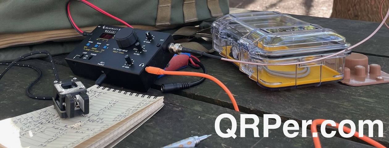
Gear:
- Xiegu X5105
- CW Morse “Pocket Paddle”
- Arborist throw line
- Weaver arborist throw line/weight and storage bag (affiliate links)
- Tom Bihn Large Travel Tray
- Rite In The Rain Weatherproof Cover/Pouch (affiliate link)
- Jovitec 2.0 mm Mechanical Pencil (affiliate link)
- Muji A6 Notepad (affiliate link)
- Monster Standard Speaker Cable 100ft (Walmart)
- BNC to Binding Post adapter
- Tools: Wire cutters/strippers, Tape Measure, Banana Jacks
On The Air
I’ll admit: I was a bit nervous putting this antenna on the air. Although I felt the X5105 ATU *should* match this antenna, I had no idea if it actually would.
Fortunately? It did.
At this point, if you don’t want any spoilers, I suggest you watch my real-time, real-life, no-edit, no-ad, video of the entire activation (including buying and building the antenna!).
Click here to watch the video.
Otherwise, scroll for my activation summary…

I was very pleased that the X5105 found a match on the 40 meter band.
I started calling CQ in CW and validated my activation by logging 10 stations in 13 minutes.
Honestly: it doesn’t get much better than this.
I logged three more stations on 40 meters CW, then moved up to the 30 meter band where the X5105 easily found a match.
I worked one station on 30 meters before heading back down to the 40 meter band to do a little SSB. I logged three SSB stations in five minutes.
Mission accomplished!
In the end, I logged a total of 17 stations including a P2P with K4NYM.

Not bad at all for speaker wire!
After the activation, I tested the X5105 ATU by trying to find matches on other bands–I was able to find great matches from 60 meters to 6 meters. Most impressive!
X5105 battery
You might recall that I attempted to deplete my X5105 internal battery at my last (rather long) activation of Lake Norman State Park. I wasn’t able to deplete the battery at that activation, but I finally did at this one.
All I can say is that I’m incredibly impressed with the X5105 internal battery. This was my fourth activation from one initial charge on May 16. The battery lasted for 20 minutes, taking me well beyond the 10 contacts needed to validate this park. I’ll now consider taking the X5105 on a multiple SOTA summit run!
Short Hike
Even thought the heat was intense and the humidity even more intense, I decided to take in a 2 mile hike post-activation. I snapped a few shots along the way.


 Improvements


I’ll plan to add more counterpoises to the speaker wire antenna as I know this will only help efficiency.
In addition, I’ll plan to build even more antennas with this roll of speaker wire. If you have some suggestions, feel free to comment!
Thank you for reading this field report!
Cheers,
Thomas (K4SWL)
Do you enjoy QRPer.com?
Please consider supporting us via Patreon or our Coffee Fund!
Your support makes articles like this one possible. Thank you!


 There are two designs: one with an on/off switch, and a newer version without an on/off switch that has auto power save. Both circuits are the same but the software for the PIC chip is different. If you build the one without the on/off switch there is a very specific sequence of connecting and disconnecting the device and it’s my opinion that the one with the on/off switch is the version that makes more sense to build. It shouldn’t matter which order you connect everything up and you simply throw the on/off switch to turn the device on and off.