Category Archives: Kits

Video: Alan (W2AEW) Builds the CFT1 5-Band CW Field Transceiver

Our friend Alan (W2AEW) has just posted a video showing the process of building, adjusting, and aligning the CFT1 5-band CW portable transceiver. If you’ve been thinking about building a CFT1 kit, this video will help guide you [update: see note from Alan below]:

Click here to view on YouTube.

Thank you for making this tutorial, Alan!

In Stock: The Ham Radio Workbench Podcast DC Distribution Panel Kit

Many thanks to Mike (KG4MTN) who notes:

Hi Thomas,
Just a note to let you know that digikey has a supply of Ham Radio Workbench DC Power Strips in stock, 43 at the time I reviewed. Product number is HRWB101.

Thought you might want to let your audience know. These are neat little kits, I really like mine!
72,
Mike Serio
KG4MTN

Thanks for the tip, Mike! These will likely sell out quickly.

I may be biased, but I love mine! Such a handy accessory and easy kit build.

Click here to purchase one via DigiKey!

KM4CFT Teases a New CW Field Radio!

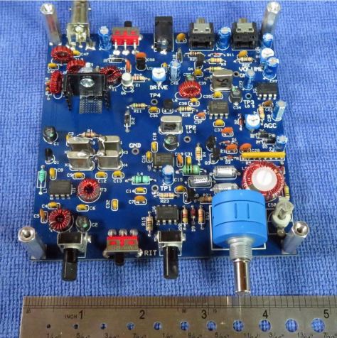
My buddy, Jonathan (KM4CFT), is close to releasing a new CW Field Transceiver kit he designed for POTA, SOTA, and pretty much any other field radio activity.

Today, he shared the following photo, which is a bit of a teaser:

Those of you who attended Four Days in May this year may have already gotten a proper sneak peek and even operated a prototype of this radio.

Jonathan tells me that he’ll be releasing details in the near future and you’ll soon be able to order the kits via Radio Dan’s eBay store [eBay partnership link] or via his website.

Of course, I’ll also post details here on QRPer.com when the new radio kit is live and ready to order! Stay tuned!

Sam’s Thunderbird Mk 1 Takes Flight: A Homebrew Radio Field Report from the American Southwest

Many thanks to Sam (WN5C) for sharing the following guest post:


Homebrew in the Field

by Sam (WN5C)

What a week it’s been!

I have the opportunity to spend a month traveling through and camping in the American Southwest (specifically, New Mexico, Arizona, and Colorado) doing archaeological work. And of course, that means the prospect to operate portable at weird times and in lots of places.

I’ve been planning for this trip for a couple of months, about the same length of time that I’ve been trying to achieve my amateur radio dream: to build a complete transceiver. So why not try to do both things at once?

This is just a quick note of my experiences in the first quarter of my trip of taking a homebrew rig into the field.

First off, I have absolutely no background in RF engineering, or electronics at all. But the literature is good and Elmers are priceless (thanks Kenn KA5KXW!). I started small, with kit projects, and then very basic transmitters.

I’ve always appreciated how much satisfaction my father gets by building things by hand, and finally I have a similar hobby. I called the radio I designed the Thunderbird Mk 1 based off the fact that I cut my CW and POTA teeth at Lake Thunderbird State Park in Oklahoma and will probably continue to work there the most. It’s a 6-band (40, 30, 20, 17, 15, 10) CW QRP transceiver with SSB receive.

The receiver is direct conversion and is an amalgamation of VU2ESE’s DC40, KK7B’s Classic 40, and W7EL’s Optimized QRP Transceiver. The VFO is an Arduino/si5351 combo based on the schematics and code written by VK3HN (who has helped me from afar, thanks Paul!). It’s crude, but I use a 6-position rotary switch to manually switch between the band-pass filters.

The transmitter is based on W7ZOI’s Updated Universal QRP Transmitter, married with VK3HN’s Arduino code that acts as the oscillator, keyer, and side tone generator. I get about 3 watts output for 40, 30, 20, a little less for 17 and 15, and about a watt on 10 meters. Like the receiver, I manually switch the low-pass filters.

Here’s a picture of the digital parts (ignore the second Arduino Nano, I thought I would need it but did not), the power board, and the filters. It’s on the bottom:

On top is the main board with the receiver, the transmitter, and T/R switching. Also, you’ll notice the green PCB. I *really* wanted to build NM0S’s Hi-Per-Mite from scratch but I couldn’t get the circuit to run right before my trip so I opted to install one that I built from a kit. It’s a fantastic CW audio filter that I can switch in and out (everyone should have at least one!).

I can switch in a little speaker and added a straight key jack. I printed the box on a 3D printer at the local library. It works great for the shack. In the sun, it’s starting to warp in the heat, so I’ll have to address this, but things still work!

Getting out the door on time with a finished radio was tough! I had finished right before I left on my trip (end of May 2024) and had no time to field test. The best I got was taking the rig to the table in the back yard and firing it up during the WPX contest.

I made amazing DX contacts on all the contest bands I had and called it good. But working superstations isn’t real life, and over the next week I’ve had to MacGyver the radio (rigging a car jump pack, an inverter, and a soldering station together at a picnic table to replace a bad transistor, for example). I think I’ve finally shaken out (literally) all of the loose solder joints and bad grounding. Continue reading Sam’s Thunderbird Mk 1 Takes Flight: A Homebrew Radio Field Report from the American Southwest
Build Your Own VK3IL Pressure Paddle: Alan’s (W2AEW) Step-by-Step Video Tutorial

Our good friend Alan (W2AEW) has just posted a video on his excellent YouTube channel showing how to build the VK3IL pressure paddle. He also explains how the key works using the schematic and gives tips for working with the surface mount components.

This paddle is an exceptional key and quite inexpensive to build!

Click here to watch on Alan’s YouTube channel.

KM4CFT’s Iambic Paddle Kit for the Elecraft KH1

Many thanks to Jonathan (KM4CFT) who notified me that his new KH1 iambic paddle kit is now available to order.

I know Jonathan has been working on this little key for a while and I’m pleased to see it come to fruition.

Click here to check it out on eBay via Dan (W7RF).

Note that this is an eBay partner link that also supports QRPer.com at no cost to you!

QMX – From Kit to Field!

by Matt (W6CSN)

The Radio

The QMX by QRP Labs is a five band, multi-mode radio introduced by Hans Summers G0UPL at FDIM in 2023. The QMX is the next logical step in the radio development journey at QRP Labs, bringing together the innovative approach to FSK modes like FT8 from the QDX and the CW performance of the QCX series. This is all done in same enclosure as the QCX-Mini which is not much larger than a deck of playing cards.

Size of the QMX compared to standard deck of playing cards.
The QMX is about the size of a deck of cards.

The keen observer will notice that the QMX also sports a built-in microphone which, along with associated circuitry, supports future introduction of voice modes by way of firmware update. Other notable features include SWR metering with protection as well as solid-state “PIN” diode T/R switching, plus the option for “high band” coverage of 20 through 10 meters in addition to the original 80m-20m version.

Most hams have, at one point or other, forgotten to throw the antenna switch, adjust the tuner, or even connect an antenna before transmitting. The SWR meter and protection really sets the QMX apart from earlier QRP Labs radios. There are plenty of sad tales on the QRP-Labs forums from QCX or QDX users that “smoked” the BS170 mosfet finals in a moment of operating into a badly mismatched load. It’s remarkably easy to do, ask me how I know!

The Build

Based on experience with the QCX-Mini and having put together several QDX’s, I admit to being hesitant to starting assembly of this radio. The level of integration in the QMX as a multi-band, multi-mode unit is probably the highest yet to come out of QRP Labs. The components that were merely small in earlier radios are absolutely tiny in the QMX, specifically the LPF toroidal cores. The main board, internal switching power supplies, display, and controls board are all sandwiched together in a tight fit for the custom enclosure.

photo showing a partially completed circuit board
Most of the electronic components installed on the main board.

The build started with a slow and methodical approach of doing a little bit each day and working in the morning when my mind was fresh and there was good light on my workbench, a.k.a. the dining room table.

The first “disaster” happened when performing the factory recommended modification to Revision 2 boards shipped in 2023. The mod calls for a protection diode to be installed across a SMD mosfet. Several leaded 1N4148 diodes were available in my “junque” box so I attempted to carefully fit one of these in the right position on the board. While soldering the diode in place I managed to lift C508, a microscopic .1uF SMD capacitor, clean off the board!

photo of circuit board with modifications
The suggested modification adding a protection diode.

Given the tools at my disposal, there was no way I was going to be able to get that capacitor back into place. Therefore, I grabbed a standard through hole .1uF cap and painstakingly got it connected in the right place, verified by lots of continuity testing.

Once finished with all the electronic components on the main board, I was feeling pretty cocky and also the completion of the project was more clearly in view. The cautious and methodical approach gave way to a faster build pace, which directly lead to the second “disaster.” While installing the headers that connect the main board to the display board, I failed to CAREFULLY READ THE ASSEMBLY MANUAL and soldered the male pin headers where I should have installed the female sockets!

This misstep might have ended the project right then and there if I had not at some point in the last year bought a proper desoldering tool. This is not an expensive automatic vacuum pump powered solder re-work stations, but rather a heating tip and manually actuated solder sucker built into one tool. Twenty-two unsoldered connections later, we were back on track. Continue reading QMX – From Kit to Field!

HRWB DC Distribution Panel Kits in stock at Digikey!

Many thanks to Mike (KG4MTN) who notes:

Good morning Thomas,

I did not know if you are aware, but Digikey has in stock about 67 HRWB 5-port dc power strip kits. I ordered one last night, they are $49.94 plus tax/shipping. Apparently these have been out of stock for some time, I am glad to see them available.

72 and God bless,
Mike Serio
KG4MTN

Thanks for the tip, Mike! These will sell out quickly, so grab one while you can, I say! I love mine.

Click here to purchase one via DigiKey!

Field Radio Kit Gallery: KD0FNR’s Rockmite 20 and Tuna Topper

Many thanks to Hamilton (KD0FNR) who shares the following article about his portable field radio kit which will be featured on our Field Kit Gallery page. If you would like to share your field kit with the QRPer community, read this post.


Rockmite 20 and Tuna Topper Pack QRP Punch

by Hamilton (KD0FNR)

Our ham radio field kit—in my mind—revolves around simplicity. I’ll walk you through a lot of details, because we have a blast with the field kit and I love talking about it. At the end of the day, it’s a kit radio and amplifier housed in a couple of cans with lengths of wire we bought at a hardware store for an antenna, a cell phone power brick, and a keyer glued together out of video game switches and an old battery case. We’ve thrown the kit into cloth shopping bags and backpacks with equal measures of success. We once patched an antenna connection using washi tape.

OK, I said ‘our’ and ‘we’, but who are we? I’m the dad of three kids—one of whom recently passed her Technician radio exam, KO6BTY—who are 12, 11, and 8 years old. Right now, they’re rarely on the radio—of course, that’s about to change—they help with most aspects of our radio outings.

Which brings up the question, what do our radio outings look like? Our outings are pretty equally divided between, camping and day trips. Our entire family has enjoyed camping—and done a lot of it—since long before I got back into ham radio. Each of the kids went on their first camping trip when they were a few weeks old.  Our camping trips range from local, public transit enabled outings—we take the bus to Pantol Campground, across the Golden Gate Bridge from San Francisco where there are two POTAs readily available: Mt. Tamalpais State Park and  Muir Woods. We also take multi-day/week trips: I grew up in New Mexico, so the kids and I frequently find ourselves back there activating or attempting to activate sites like Villa Nueva State Park, Organ Mountains National Monument, and Cibola National Forest, among others. These are the outings that have led to large-ish battery selections you’ll see below.

Our day trips are quick runs along various local bus, train, and ferry lines with a hike tacked on the end. Within the peninsula that encloses San Francisco, we have several POTA locations and two easily reachable SOTA locations. We pretty frequently bus to a spot, and then spend a few hours hanging out in a nice park getting some radio time.

Having said all of that, you might have guessed that our kit would be optimized for easy travel. You’d be right. Now, finally, let’s talk about the kit!

Radio Details:

All of our equipment is home-built. It’s evolved over the last year-and-a-half into he tidy kit you see above. Finally having a ‘typical’ kit picture is actually what inspired this article.

Equipment List:

[Please note: All Amazon links are affiliate and support QRPer.com.]

  • Rockmite 20
  • Tuna Topper
  • One 20 ounce can Dole Pineapple Slices (emptied—see support crew; and cleaned)
  • Two RJ-45 breakout boards
  • One spool butcher’s twine (two if you’re feeling bougie)
  • One Imuto power brick that supplies 15 V when funneled through:
  • One Adafruit USB Type C Power Delivery Dummy Breakout – I2C or Fixed – HUSB238
  • Two banana jack sockets (plus a few more for spares)
  • Forty feet 12 gauge insulated/stranded wire
  • Twenty-five feet (or so) RJ-45 Ethernet cable (scavenged from the parts bin at our local maker space)
  • One antenna launcher (scavenged from available fallen tree limbs onsite)
  • One donut Bag from your favorite donut store
  • One roll of washi tape

The Rockmite is a rock-locked radio with two available frequencies that are 500 Hz apart from each other. That makes our antenna design really simple; we’ve got a dipole that’s trimmed to be resonant at 14057.5 kHz. Project TouCans puts out a QRP maximum 5 Watts. Our field kit has evolved to that 5 Watts though. We started out with the Flying Rockmite at 250 mW, then we made a power bump to 750 mW, and then with the addition of a Tuna Topper amplifier and a lot of experimenting we finally achieved a QRP maximum 5 Watts output power.

The QRPp Rockmites–having so little power combined with lots of somewhat confusing reading about antenna matchers and coaxial cable and baluns–led to the original Flying Rockmite. “Do you know what makes you not have to discuss feed lines?” I reasoned, “Not having a feedline.” And so, the RockMite was inserted into the dipole. I brought the keyer controls down to me and sent the power up along an Ethernet cable. Continue reading Field Radio Kit Gallery: KD0FNR’s Rockmite 20 and Tuna Topper

NM0S introduces the NorCal 40B transceiver kit

Dave (NM0S) has updated the NorCal 40A transceiver kit. Here’s the information from NM0S’s website

NM0S Electronics has received permission from the Wayne Burdick N6KR to produce an updated version of the legendary NorCal 40A CW Transceiver.

The new ‘B’ version kit overcomes the issues with obsolete components that caused the original kit to end production.

The NorCal 40B follows the design of the original faithfully, while adding a rugged pre-drilled, silkscreened enclosure!

Click Here to order ($150 US)!