
I really like homebrew radio. I’m also seeing a pattern: I build through the winter and the spring, get rusty at CW, and then spend the summer operating POTA until my ears bleed. So it’s good to be back! Here’s a quick report of a new radio I built and its maiden voyage.
 For the past eight months I have worked on what I call the Thunderbird (v2) named after my local state park, Lake Thunderbird. It’s an 8-band (80-10 meters) 5-watt CW transceiver with SSB receive. I emphasized the latter (decent crystal filter and big speaker/audio amplifier) because while I don’t often use a microphone, listening to voice is both comforting and exciting – I love when the VK and ZL stations drift in late at night. It also works as a somewhat competent general coverage receiver for short wave listening. I built it to operate both in the shack and on a picnic table, it unfortunately is a bit heavy because I got greedy and kept adding bands.
 I guess I “designed” this radio, but as I discussed before on this site I’m just a guy with no engineering background who learned to solder and read a schematic diagram. But by doing so I could understand and modify the clever circuits from the radios we love and then figure out how to make them play nicely together.
I built the radio using Manhattan construction on copper boards, and then stacked these and fit them into a metal project box with 3D printed front and rear panels. It’s a bit fiddly and messy, but I feel like I’m ready to challenge my family to a game of Operation! The nice thing about stacking the boards is that I can shield the receiver from the transmitter and digital components.
 The bottom board houses the band-pass filters, receiver, and audio chain. This was my first attempt at building a superheterodyne receiver so I was a bit nervous (although this video calmed me down). The receiver takes inspiration from John Dillon’s (WA3RNC) TR-35. He uses a clever design to narrow (for CW) and widen (for SBB) the crystal filter. I also cribbed his excellent idea for the LED signal-strength meter. The audio chain was modified from the Elecraft KX1 which includes an AGC circuit. I learned last summer how important AGC is when I was on Vail Pass in Colorado and actually fell out of my chair and groaned in pain when a guy with an amp called me back. I also hand built an NM0S Hi-Per-Mite to switch in when I want a steep 200-Hz filter. This is an awesome circuit that you can buy in kit form.
Like I mentioned, I got greedy and experienced project creep. Honestly, I would have been super happy with 40, 30, and 20 meters, and 17 would be nice. But so would 15, and 10, and even 12 (a band that I only have a handful of contacts on ever). And why not 80 meters? So I modified Steve Weber’s (KD1JV) Tri-Bander relay-switched band-pass filter design to add them all. I also figured out how to build a preamp for the high bands. I built a secondary audio amp to drive a 3-inch 3-watt 8-ohm speaker for annoying my family at night.

The top board houses the transmitter and the digital components. The transmitter is based on Steve Weber’s design because it’s perfect and is used in some form by many QRP CW rigs. It gives me between 4-6 watts output on all bands. Like with the receiver, I used his design for the low-pass filter board.
The heart of the transceiver is an Arduino/si5351 combination and the Arduino code written by Paul Taylor (VK3HN). Besides doing the heavy lifting of aiding me pull audio out of the ether his code and associated circuits are versatile and clever, including automatic filter switching, CW messages, and both keyer and straight key support.
Although I am mildly terrified of AI, ChatGPT helped me add all kinds of bells and whistles (on my own I’m not a very good programmer) such as RIT, audio filter switching, keyer speed control, and a simple but detailed display that shows the relevant information. The panel controls are all knobs and switches.

Between the sub-par band conditions as of late, and my neighborhood’s increasingly nightmarish RFI, testing the radio’s real-world performance was difficult. Luckily I have an IC-703 on the bench and it keeps me sane. The Thunderbird isn’t as good but it’s maybe 85% of the way there (when I turn off the DSP and noise blanker on the Icom)? It has been disconcerting when 10-meter FT8 isn’t coming through, but apparently that’s the sun’s fault and not mine. But this radio was built for POTA, so onwards to my park!
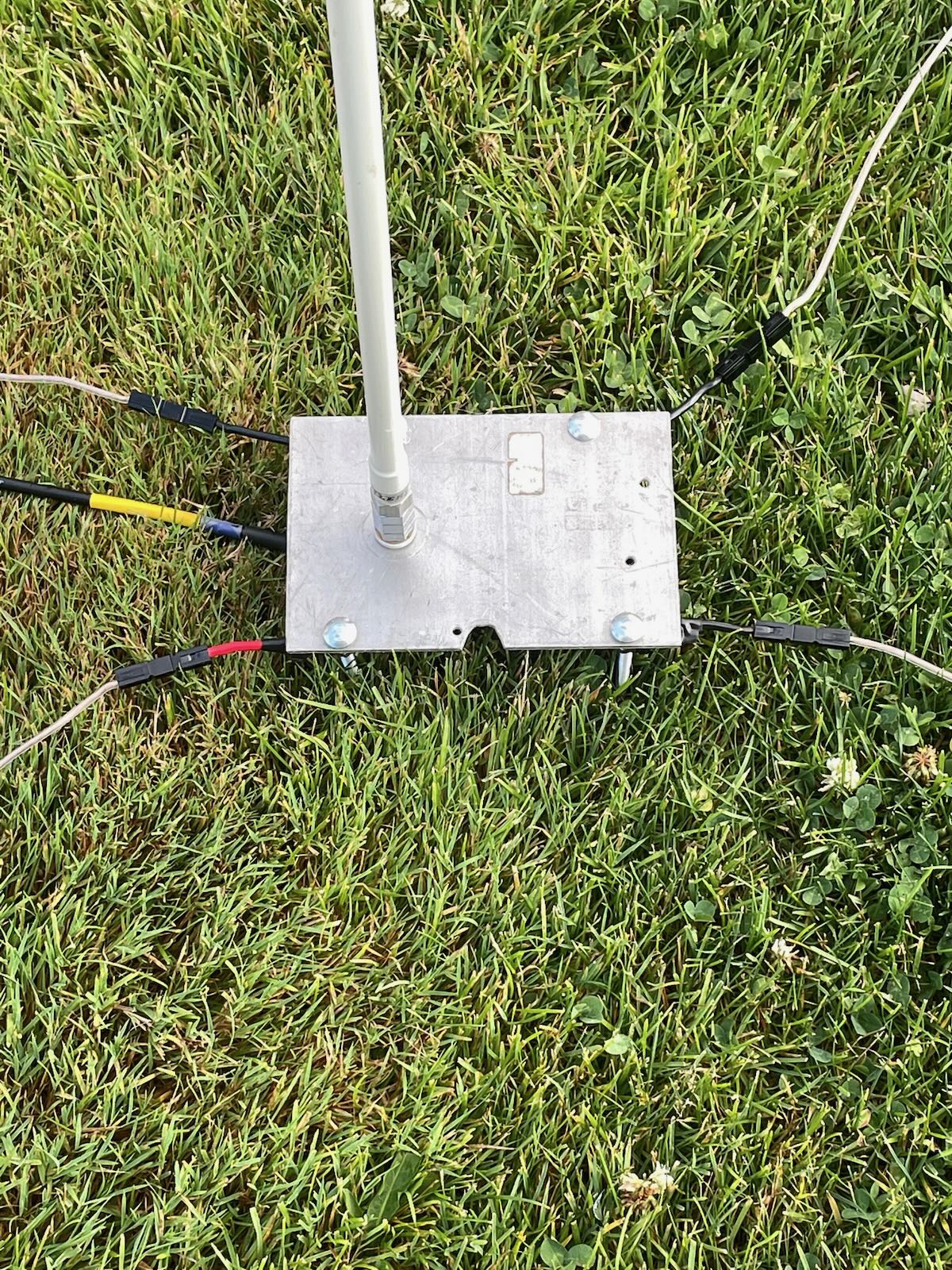
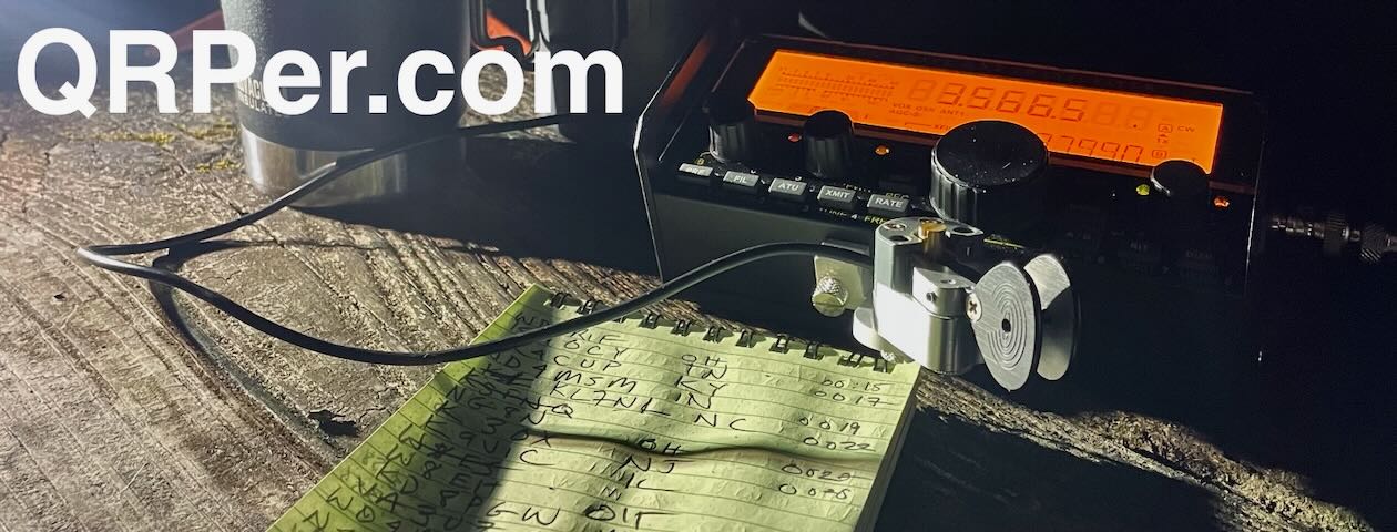
 For an activation it was a rush job. I had just finished with the fixing a few loose connections when I realized I had about an hour of time before picking my kid up from camp. So I headed to the park with the radio, my favorite easy-to-deploy antenna [QRPer affiliate link], and my ATU-10 (doubles both as a tuner and check to see if the radio actually works).
There has been a lot of rain here lately so my usual spot was underwater. As I was setting up on the high ground a car drove past me multiple times. I figured I was either in trouble or it was a ham, and fortunately it was the latter. Larry (WA5NTF) and I had a nice chat and he graciously drove across the bay to absolutely clean up on digital. For me, I spent about 30 minutes on 20-meters, got 25 contacts, and then failed on the high bands. This is my first solar-cycle peak: get it in gear, Sun.
 A few observations: I really liked the speaker! I was away from others and could use it without invoking ire, and it was freeing. Same with the message function which helped because it wasn’t a day of pileups. I also am so used to an S6 noise level on 20-meter SSB that when I first started the radio I assumed it was broken, so quiet. What a difference being out of the city makes.
But it worked! I have some trips planned for the summer and fall to the Southwest so I can’t wait to lug this box to some weird places. And I’ll hopefully be operating locally quite a bit more. Hope to hear you on the air, hopefully on the high bands!
And a postscript, I’m not going to be a homebrew proselytizer, but if you have an inkling to try something new a great project is the SolderSmoke direct conversion receiver (I started with something similar). On this page there is a link to their active Discord server with friendly people and lots of guides on how to hand build a 40-meter receiver. Paired with a simple transmitter it would make POTA (even more) ridiculously fun.
72, Sam