Category Archives: How To

Karl Heinz’s Pocket-Sized Digital HF Station

Many thanks to Karl (K5KHK) for sharing this guest post, which originally appeared on his blog, Karl Heinz Kremer’s Ramblings:


A Digital Station in Your Pocket

by Karl Heinz (K5KHK)

How small can a complete station to work FT4/8 be? With the QRP-Labs QMX, we have a transceiver that certainly fits the bill for a small station. By itself it can only be used for CW, to use the digital modes, one has to combine it with a computer. Even the smallest laptop is too big the fit into the pockets of my cargo pants – we are trying a pocket sized station after all 😉

In this article, I will describe how to use a QMX transceiver and an iPhone to activate a POTA park with FT8.

The Components

My QMX is the original that was released at FDIM 2023, so it covers 80m to 20m. Mine is serial number #20.

My iPhone is small enough, but unlike Android based phones, the QMX cannot be connected directly to the phone. Apple sells a “camera adapter”, which plugs into the phones Lightning port on one side and provides a USB connection on the other end. $29 for the original Apple part was a bit hard to swallow, so I opted for something cheaper straight from China’s “we clone everything” factories: https://amzn.to/3WDSfUc

[Please note: All Amazon links are affiliate that support QRPer.com.]


The picture shows both a USB and a lightning port on the adapter. This should allow the phone to be powered/charged while the adapter is being used – more about that later.

Another limitation is the antenna: The QMX does not have a built-in antenna tuner, and even my QRP sized ZM-2 would have to live in a different pocket 🙂 My plan is to use a resonant antenna so that I would not need a tuner.

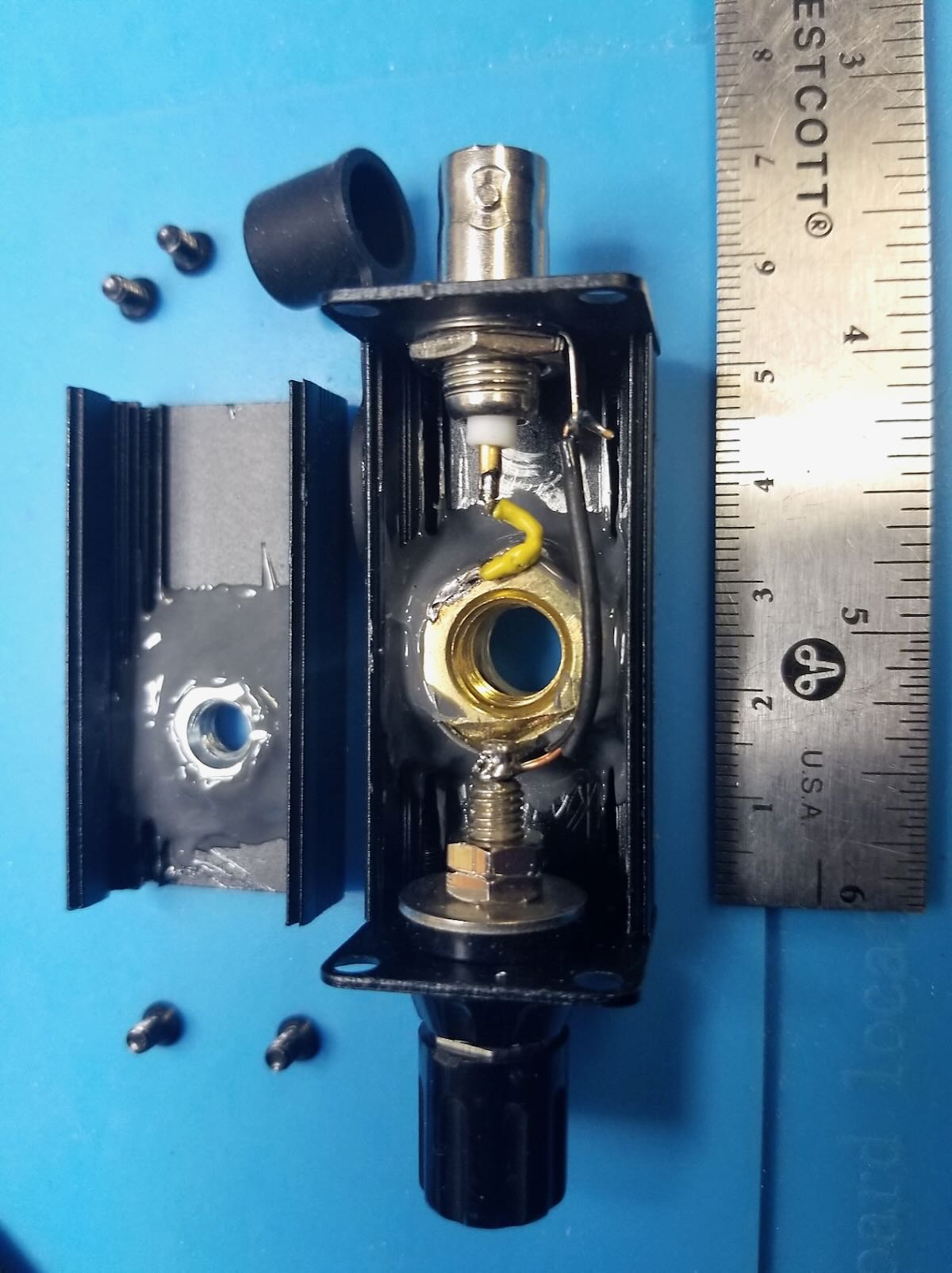
The easiest antenna with a good match is a dipole, but that is a bit more challenging to deploy in the field, so I opted for an end-fed halfway (or EFHW) antenna with a 49:1 transformer. I 3D printed a winder that allowed a BNC connector and the transformer to be mounted on the wire winder:

The design came from Thingiverse: https://www.thingiverse.com/thing:2871679

Because I am using a different toroid for the transformer, I had to remove the “bump” that is holding the toroid in place. Going forward, I may change the design a bit more to have so that I can fit more wire on the winder.

For those familiar with the transformers usually used for EFHW antennas, the picture shows two things that are different: As I’ve already mentioned, I am using a different toroid (the Fair-Rite 2661102002 core, which is a type 61), and a different winding pattern. More about that in a future post.

To power my station, I am using a TalentCell rechargeable 12V power bank:  https://amzn.to/3snTyr8

First Test

With everything in place, I tried to make a quick FT8 contact from home with this setup, but with my “big” EFHW antenna in my backyard. Because it was just a quick test, I did not even bother to hook up the charging cable for my phone (more on that later).

The software I am using is iFTx, which supports both FT4 and FT8.

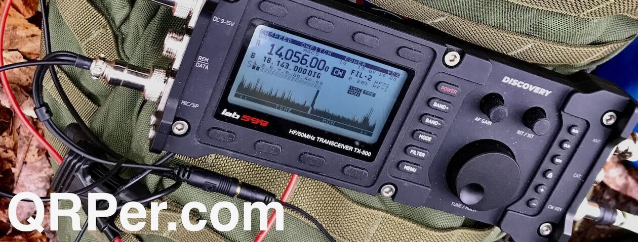
I connected the phone to the adapter from above, connected the adapter via a USB cable to the QMX, and connected the QMX to a 12V power supply (unlike anywhere else in ham radio, 12V here means 12.0V and not the usual 13.8V), and hooked up the antenna to an antenna tuner and then to the EFHW in my back yard.

I answered an FT8 CQ call and successfully completed the FT8 exchange. The software does the automatic sequencing of the different messages, so it is very straight forward to use. With this first contact, I verified that the iPhone/adapter/QMX setup does work.

The Real Test

The next attempt was while camping at Hamlin Beach State Park (US-2068). I set up everything just like at home, but because I was planning on being on the air for a while. I also hooked up the cable to charge my phone while I was operating.

I was able to receive stations, but could not transmit. What made the troubleshooting more complex is that during setup, I created some sparks (that is why I do not like the barrel connector for power). I was pretty sure that the QMX was not involved, but not being able to transmit kind of suggested that I killed the finals. So I put everything away and used my KX2 instead.

Back home, I did some troubleshooting and hooked up a straight key to the QMX and it worked: I was able to finish a few CW QSOS without a problem, so the finals were definitely OK. I then set up the system again for FT8, and sure enough, I was able to make a contact. Because it was a quick test, I did not bother to use the power cable for the phone. By now, most of you probably know what the culprit was, but because I did not spell things out like this, I was still in the dark.

Success At Last

Fast forward a few more days… We went back to Hamlin Beach State Park – but this time to the picnic area – and I set up my station again. And sure enough, once everything was set up, the QMX did not transmit. This is when I took a step back and reviewed everything I had done so far, and slowly I came to the realization that when I provide power through the adapter to the phone, the QMX would not transmit.

I was able to finish my FT8 activation with my pocket sized digital station. I did run into one problem however: iFTx allows to automatically determine one’s grid square – which of course is important for FT8. When I enabled that, it correctly put me into FT13 at first, but a few QSOs later it switched me to JJ00aa – I reported this as a bug to the developer.

Using iFTx with the iPhone

The connection from the phone to the QMX is audio only. iOS does not allow an application to open a serial port connection (unlike Android). This means that the QMX will not receive any frequency information from the phone, and also no PTT signal. For this setup to work, the operator has to make sure that the QMX is tuned to the correct frequency that the correct band is selected in iFTx, and that the QMX is set to VOX mode (this is in the Digi Interface menu).

When configuring iFTx, it is possible to select a “Special Interest Activity” like POTA. This is then added to the CQ call as in “CQ POTA K5KHK FN13”.

As I’ve mentioned before, the application will automatically sequence the correct messages when a station answers the call.
Once the QSO is completed, it will be logged to the iFTx internal log, which can be exported via the usual “send to” methods available in iOS (e.g. email the log, save as a file, …).

When exporting the log, there is a choice of exporting everything, or only the new QSOs since the last export. This will create an ADIF file, which can be submitted to the POTA program, or imported into any other logging program.

At the end, I was successful in building a “pocket sized” digital station based on the QMX, I just need a fully charged phone and cannot depend on charging it while operating.


Click here to check out more articles from Karl on his blog!

W2AEW’s Trapped EFHW Antenna Tutorial: Building a Smaller, More Versatile Solution for Portable Operations

Many thanks to Alan (W2AEW) for the following guest post:


Trapped EFHW antenna story (it’s all Vince’s fault)

by Alan (W2AEW)

One of my favorite antennas to use for POTA activations is a 40m EFHW wire.  When properly tuned and deployed, it can be used on 40, 20, 15 and 10m without the use of a tuner (although, I really don’t mind using a tuner when I need to).  Most of my activations are on 40 and 20m, so those bands are covered easily.  It can be used successfully as a sloper, an inverted vee, or a combination of these (whatever the trees or support structures allow).  It is efficient, inexpensive to build, lightweight and effective.

There are a few downsides to this antenna.  The first is that it is approximately 68 feet (almost 21 meters) long.  That’s a lot of wire to get in the air.  Some POTA sites just don’t have that much room or support structures to effectively use this antenna.  Another downside is that it doesn’t naturally support operation on the 30m band, another favorite of mine.

A few weeks ago, I watched a video from my friend Vince VE6LK entitled: “Discover the secret ingredients to build a trapped EFHW antenna”. This piqued my interest…

The video introduces a design for a 40/30/20m trapped EFHW.  The fact that it covers the three bands I use the most, and would be shorter than my trusty full-sized 40m, and give me 30m to boot, got me excited to learn more.

Vince used a pair of traps (30m and 20m) that are offered in kit form by Tim Sherry, N7KOM.  Here is a link to kit on Etsy.

Image Source: Tim Sherry, N7KOM

These are exclusively for use at QRP power levels – perfect for my application.  I placed my order immediately after watching the video.  The build instructions are very detailed, including how to tune the traps, which is critical in getting the antenna to work.

Image source: SparkPlugGear

He also used a 49:1 UNUN from SparkPlugGear.  I’ve had one of these in my POTA kit for a while, but only used it occasionally.  This was another good reason to proceed with this antenna build.

Of course, you could also use the QRP UNUN kit from KM4CFT that I made a video about earlier this year.

I created a video that showed how to assemble and tune the traps.  Tuning can be a little tricky, and then stabilizing the turns/spacing to preserve the tuning is critical – not hard, just takes a bit of patience.

With the traps built and tuned, the next step would be to build and tune the antenna itself.

I was able to find the time this weekend to do just that, and make a video of the process.

Details of the resulting wire segment lengths are in the video.  It is important to note that if you decide to build this antenna, your wire lengths will likely vary from mine.  Several factors will effect the resulting lengths (details of the UNUN used, the trap construction, etc.).  My video goes through the process I used to build, tune and test the antenna.

“The proof is in the pudding” as they say.  It was time to actually run a POTA activation with this antenna.  The overall length of the antenna was about 43 feet (about 13.1 meters), which is about 2/3rds the length of the 40m EFHW.  This opens the possibility of using my 12 meter Spiderbeam mast (video review) as a support rather than just relying on a tree branch.

The weather here in NJ has been oppressively hot and humid with heat indexes over 100F, so I opted for a morning activation, before the heat really built up.  The intent was to get some contacts on all three bands, even though 20m probably wouldn’t be very active.

I setup at my “home” park – Washington Rock State Park, US-1635.  I decided to setup the Spiderbeam mast as the support for the new antenna:

The rig was my trusty KX2 with the BamaTech TP-III paddles:

I only had about an hour to dedicate to operating before the family activities for the day, so I figured I’d start on 40m and get most of the “ten” there first, then move on to pick up a few on 30m and 20m.

I was able to put 14 contacts in the log, under “so-so” band conditions, which at least a few on each band, several of which were park-to-park contacts.

Here’s the map of the “reach” that the new antenna had during this short activation:

Overall I am quite pleased with the antenna’s performance.  The near ideal band coverage for my typical activations, and the ease of deployment compared to the full-sized 40m EFHW make this antenna a great addition to my POTA kit.  I suspect it will get a lot of use!


Resources:

Construction Notes: VO1DR Monopod Antenna Mount

Many thanks to Scott (VO1DR) who shares the following guest post:


Construction Notes – VO1DR Antenna Mount for Camera Monopod

by Scott Schillereff,  VO1DR

Further to my article about radio during trip to Portugal, a number of readers asked for details on how I mounted my whip antenna system to my camera monopod for /P use.  Here are some photos and notes on this.

General notes:

  • This is a “straight-through” design.  Just direct connections from the BNC center pin to whip (via brass nut), and BNC housing to radial connector.
  • This is not a cook-book construction article, rather just a show-and-tell of how I built mine.  You can use what you have on hand to build something similar.
  • I suggest you start with your telescoping whip, so you know the size and threads for mounting bolt.
  • You could use any type of connector for the radial (wingnut, knurled nut, spade lug, alligator clip, whatever you like).  I prefer banana jacks since a) I can push in the radial banana plug fast, b) the plug is a weak release point (pulls apart if someone walks into the radial), and c) I can easily attach additional radial wires, if desired.
  • Use a strong case (metal clamshell or cast aluminum work well).  With the whip extended, there can be substantial forces (bending moment) from wind or handling. A tiny plastic case would be fractionally lighter but might fail.
  • For size, the one I used (25 x 25 x 50 mm; 1” x 1” x 2”) is about as small as I would go.  It needs to have a big enough footprint to sit firmly on a camera mount fitting.
  • Use high heat (e.g., Weller 100-140 W solder gun) when soldering the center pin wire to the brass whip mounting nut.  Solder the wire to the brass nut before you epoxy the nut.
  • I custom made the white plastic insulating bushing (where whip screws in). This was from a nearly-right bit from my junk box.  You can be creative here.  You could also epoxy on short piece of close-fitting, thick-walled PVC pipe around the outside of the whip mounting hole as a supporting sleeve to give some lateral support to whip when it is screwed in.
  • Dry-fit everything (before epoxying) to make sure nothing touches that shouldn’t and you can screw in the camera nut and whip fine.  Test proper continuity of center pin and radial connections to BNC fitting.  Once glued, there’s no going back!
  • For surfaces to be epoxied (metal nut sides and bottom, insides of mounting case), slightly roughen with sandpaper or jewellers file, then clean with isopropyl alcohol and Q-tip.  This will increase adhesion and strength.
  • Use good-quality, high-strength, long-cure epoxy (e.g., JB Weld), not el-cheapo 5-minute epoxy from the Dollar Store.  LET THE EPOXY COMPLETELY CURE BEFORE MESSING WITH IT!  Just walk away from it for a day… (your patience will be rewarded).

Figure 1 – VO1DR Antenna Mount, clamped onto top of monopod.  Coax goes to BNC on left; whip screws into top; raised radial connects by banana plug on right

Figure 2 – Antenna mount unclamped from top of monopod.  The black plastic fitting (at right, with wedge-shape) fits into slot on platform at top of monopod (at left) and clamps in with cam arm.  Large steel screw attaches wedge fitting to antenna mount case. Ruler shows scale of things.

Figure 3 – Antenna mount case (right) unscrewed from camera mount fitting.  Steel screw is standard camera mount size (1/4-20 thread size).  Black silicone cap keeps dust out of BNC connector.  If your camera mount does not have a detachable wedge fitting (like the one on the left), you would simply screw the camera mount screw directly into the bottom of the antenna mount case.

Figure 4 – Top of monopod dissembled to show (clockwise from top): black monopod tube with telescoping whip stored inside (stainless steel with 10 mm brass mounting bolt), antenna mount case, detachable camera mount fitting, and round top plate of monopod.  For my monopod, I had to remove one tiny screw and apply gentle torque to break a weak glue joint of this round piece on top of the monopod leg.  It remains a snug hand fit (no screw needed).

Figure 5 – Fully assembled whip antenna mount with wiring.  Radial (blue wire) with tie-off cord (yellow) at left; RG174 coax (5 m) at right.  Whip is only ever screwed in hand-tight.  Deploying in the field, I first tie off the monopod to something (park bench, picnic table, fence, tree), then screw the collapsed whip into the antenna mount and clamp mount on top of monopod, then plug in radial and tie the yellow cord off to something (straight out at 2 m height or slope down to ground anchor), and finally connect the coax to the rig.  When all in place, I carefully raise the whip (slowly, with two hands to reduce bending forces).  Take-down is all in reverse.

Figure 6 – Detail of antenna mount case.  Case is 50 mm x 25 mm x 25 mm aluminum clam shell box with square metal end plates.  These end plates are screwed in to hold the two halves together.  White plastic bushing provides additional lateral support for the whip when it is screwed in.  The bushing is glued to outside of case with CA (Krazy) glue.

Figure 7 – Inside of antenna mount case.  On left, a ¼-20 steel nut is epoxied to inside of case with strong JB Weld epoxy.  In main case, a 10 mm brass nut is epoxied to inside of case with an insulating washer beneath.  This brass nut connects to the whip and is “hot”, so must be insulated from the black aluminum case.  Yellow wire connects center of BNC to brass nut (soldered).  Black wire connects ground side of BNC to radial banana jack.  Use plenty of epoxy; there is a lot of force exerted on the steel and brass nuts.

Figure 8 – Detail of inside of case.  Note separation of banana jack solder post and edge of 10 mm brass nut.  Solder yellow wire to nut before epoxying in nut.

Hope you find this useful.  Just use what you have on hand and some ingenuity to make yours!

Best 72, Scott  VO1DR

QRP in Thailand: Drew’s Journey to Get Licensed and On the Air

Many thanks to Drew (W8MHV) who shares the following guest post:


QRP in Thailand

by Drew (W8MHV)

I travel to Southeast Asia each year and usually have a few weeks in Thailand, but this year we planned on a longer stay. My XYL (N8MHV) has family in Thailand and we own a condo in downtown Bangkok. This year I was intent on getting my Thai ham license; I have never previously been licensed there.

You might be surprised to know that Thailand doesn’t make it easy for a casual American visitor to be awarded a ham license, even though the country has a bilateral agreement with the US on licensing.

For starters, you must have a visa for a long stay. A visitor can stay in Thailand for 30 days without a visa, and I have always limited my stay accordingly. But this year we stayed for of two months and getting a visa was necessary. That wasn’t especially difficult once my Thai-speaking wife helped figure out the necessary paperwork. In Thailand my wife’s calls to government offices led to a contact with the Radio Amateur Society of Thailand (RAST). Once I joined the organization, they helped push through the application and award of the license.

The RAST Secretary whose nickname is Top was a very great help. I felt like this was a big achievement as there are fewer than 1,000 ham licensees with HF privileges in a country of about 70-million.

QRP operating from anywhere in Southeast Asia requires great patience. This is because if you operate in a DX location, then everyone you work is DX to you, as by definition there are few if any local stations!

I brought my newly-acquired Elecraft KH1 for on-air use. Its tiny size made it easy to pack for overseas travel. It worked flawlessly, but the built-in whip antenna was far less useful than a 20.5 foot random wire with counterpoise I included in my kit.

Operating the KH1 from my condo.

In my 12th floor condo noise levels were terrible—typically S7, but at the top of the building on the 24th floor there is a garden where the noise levels were a manageable S3. See the photo above.

I also operated from an island in the Gulf of Thailand at a resort and noise levels there were even more quiet, as you would expect. Also, this was a comfortable operating location as the photo shows.

During my stay propagation conditions were poor mostly and I struggled to work any stations. A typical example is my final night in Bangkok I repeatedly called a station in Hong Kong whose signal was about S5, but I never got an answer. It was about the closest station I heard, but the signal path was about the same as the distance between New York City and Caracas, Venezuela.

I have operated from other Asian locations with QRP radios many times and the results have varied, chiefly depending on the kinds of antenna I could erect. Sometimes it has been lonely, other times control of a big pileup has been a challenge.

Finally, a few thoughts about the KH1.

It is an unparalleled performer for its size. It has most features you would want and its ergonomics are good. The weakest point was the paddle set, and since returning, I have replaced them with the KM4CFT aftermarket set. That said, in my travel to Thailand next year, I think I will take a KX2. It offers a few more features at a small increase in packing size.

Thanks for listening es 73 de W8MHV

Build Your Own VK3IL Pressure Paddle: Alan’s (W2AEW) Step-by-Step Video Tutorial

Our good friend Alan (W2AEW) has just posted a video on his excellent YouTube channel showing how to build the VK3IL pressure paddle. He also explains how the key works using the schematic and gives tips for working with the surface mount components.

This paddle is an exceptional key and quite inexpensive to build!

Click here to watch on Alan’s YouTube channel.

Alan demonstrates how to quickly tune the TR-45L’s Z-Match Tuner

Our friend Alan (W2AEW) just published this excellent short video demonstrating how to quickly tune the Penntek TR-45L’s Z-Match ATU. Of course, this same technique can be applied to the Emtech ZM-2 or any other manual Z-Match tuner:

An excellent tutorial, Alan! Thank you!

Getting Started with HF Digital Modes (Without Breaking the Bank)

Many thanks to Joe (N0LSD) who shares the following guest post:


Getting Started with HF Digital Modes – Without Breaking the Bank

by Joe (N0LSD)

Amateur radio can be an expensive hobby:  the reasons are myriad, made more difficult for newcomers because they tend to not have the experience to know what their requirements might be.  Brick-and-mortar stores where one might bounce ideas off knowledgeable staff, browse the aisles, and walk away with a suitable set-up are pretty few and far between.  Similarly, asking on various internet forums will often be met with, “It depends…” –followed by a wall of text filled with jargon and terminology that can be…intimidating.

For newcomers that maybe don’t have the time to invest in learning CW right off the hop, and perhaps get a bit of mic fright, digital modes such as FT8, JS8, and the like tend to be a great fit.  While “shack-in-a-box” solutions by the big-name manufacturers offer convenience, this convenience comes at a price that can be cost-prohibitive.

What follows is a QRP digital modes kit that I’ve experimented with over the last year.  No single piece of this kit cost more than US$150, and the entire kit can be had for under US$600.  What’s more, nearly everything can be purchased from Amazon.

We’ll start with the most expensive part of this kit:  the radio, which is the Tr(u)SDX.  It can be had on Amazon for US$138, and covers 20m, 30m, 40m, 60m, and 80m bands.  It is a quirky little radio with a sub-par speaker and a tiny little microphone.

The Tr(u)SDX is just about as bare-bones as one can get with an HF transceiver, and is decidedly a compromise.  However, unlike other ultra-compact transceivers, this one will do CW, it will do voice, and it will do *any* digital mode.  It can run on USB power at 1 watt output (micro-USB port on the side of the case); but it can also run on 12v (nominal) power via a 5.5mm x 2.1mm barrel connector on the top of the unit.

I’m powering this radio with a US$43 battery bank (Romoss Sense8P+), and a USB-C to 5.5 x 2.1mm cable (US$8.99) –both available on Amazon.  This battery bank will keep the Tr(u)SDX going for hours –long enough to do multiple POTA activations.  And, because there’s no special adapters, the battery bank can be re-charged in the same manner as a cell phone –or even off a small solar panel.

The sound card interface is the Digirig (US$57) with a US$19.97 cable that is TRRS 3.5mm on one end, and breaks out separate Mic and Speaker 3.5mm TRS.  Now, I will say that a recent firmware revision on the Tr(u)SDX has been demonstrated by the developers of the radio to allow for audio through the micro-USB connector of the radio – so the use of a sound card interface *may* be redundant.  However, in viewing the demonstration video for this, it seems rather dependent upon finding the right micro-USB to USB-A cable; with no clear indication on where one can obtain a cable that meets the specification.  Now, add a USB-C to USB-A or a USB-C to USB-C cable to interface with the computing device, and we’re in business!

So far we have a radio, power, and a way to get sound in and out of the radio.  Now, let’s talk about antennas.  Of course, one can homebrew an antenna for the cost of parts and time in construction and testing.  For the kit I’m using, I went with the N9SAB OCF Dipole –specifically because I do a lot of 80m QRP work.  Also available from N9SAB is a 6m-80m random-wire end-fed for US$89.99 from his eBay store.

If using a non-resonant antenna, an antenna tuner will be needed:  I went with the ATX-100 (US$126 from Amazon).  The reason I went with this is because it recharges with USB-C, which is consistent with everything else in this kit.

For coax, I personally use Times Microwave LMR-240 –a 50-foot length terminated in BNC is US$65 on Amazon.  For something less bulky, perhaps RG-316 from ABR Industries (abrind.com) might fit the bill  The ABR-240 coax at 50-feet in length is US$58.  For a jumper from the tuner to the radio, I use a 3ft RG316 cable from Amazon – which cost me US$13.99.

All that’s left is a device to run software…this can be a Raspberry Pi, or one’s laptop, certainly –however, these are bulky and require special power…and are a pain to re-charge easily.  Another solution is something one might already have:  an Android smartphone.  There are apps (some free, some paid) for RTTY, PSK31/63, WSPR, SSTV – these have been out for some time.  Additionally, one can do many of the modes contained in FLDigi, using the AndFLMsg app (not available on the Play Store –one has to download the .apk file from a 3rd party).  However, what I’ve been using –especially on POTA activations – is FT8CN.  This allows for full-function FT8 using just an Android phone –which can also be charged via USB-C.

[Note: eBay, Amazon and ABR links below are affiliate/partner and support QRPer.com at no cost to you]

Tr(u)SDX $138.00 Amazon
N9SAB Random Wire End-Fed $89.95 N9SAB eBay Store
ATU-100 Antenna Tuner $126.00 Amazon
RG316 Coax Jumper (3ft) $13.99 Amazon
USB-C to 5.5×2.1mm cable $8.99 Amazon
ABR-240 50 ft Coax $58.00 abrind.com
Romoss Sense8P+ Battery Bank $42.99 Amazon
DigiRig MobileSoundcard Interface $49.97 digirig.net/store
uSDX Cable for DigiRig Mobile $19.97 digirig.net/store
Total $547.86

This kit is –for sure– a compromise:  one isn’t going to bust pile-ups or win contests with it  However, for a “starter kit” that can easily be carried in a small backpack that can not only be used for HF digital modes, but also can do SSB voice and CW, it will at least get an operator on the air and enjoying the bands –without breaking the bank.

A Case for Making the Morserino Your Ultimate Traveling Morse Companion!

Many thanks to Paul Patsis (W7CPP), who shares the following guest post:


A Case for the Morserino-32

by Paul Patsis (W7CPP)

Morse Code is more popular than ever now. More and more Hams are discovering the joy of CW and the advantages it brings to communications from Parks, Summits, and remote locations as well as in our own back yards and QTH. It’s astonishing to witness how we can reach far corners of the world on only 5 watts with small and lightweight radios and antennas.

CW is a productive and rewarding mode of operation and like all worthwhile endeavors we get out of it what we put into it. It takes commitment and dedication to become a proficient Morse Code Operator and fortunately for all of us we have more tools available to us than ever before.

One of those tools is a powerful and small training and learning tool called the Morserino. It is a very capable little device that incorporates many features designed to help a Ham achieve proficiency at Morse Code.

When it comes to learning Morse Code, there is no substitute for time and repetition. Akin to leaning a new language the more you can immerse yourself the better you will become. Practice tools on the Internet, the Morserino, Organizations like the Long Island CW Club and “Code Talking” every day are great ways to get up to speed and increase proficiency.

Practice, practice, practice is the key.

I have found the Morserino to be a very valuable tool and wanted to find a way to take it along safely on my travels. Borrowing a page from my fellow hams who are activating parks and summits, I sought a way to protect the Morserino  whether traveling by land, sea or air. Whether in a backpack, suitcase, or other travel bags how could I keep the little Morserino protected and yet be ready for use?

To answer that question I started do some research on how people kit out their gear for field radio operations. I’ve seen good use made of the ubiquitous Pelican Micro M40 Case for lots of Ham Radio Gear and most recently for the Elecraft KH1.  I wondered if the mighty little Pelican case would work for the Morserino? I gave it a try and discovered that  with no modifications it is a great option for bringing your Morserino along on all your travels.

The setup that worked for me required very little to make it a nice and safe fit.

The first thing I did was to remove the very small spacers in the bottom of the Morserino Case that comes with the radio.

Those spacers are generally included to give a bit more space under the unit to accommodate the battery that is put underneath to power the Morserino.

I found that by using Velcro to hold the small battery in place those spacers are not needed, and the result is that it lowers the profile of the Morserino by about ¼”. This is just enough clearance to allow the top of the Pelican Case to close and not be obstructed by the dummy load on top of the antenna.

Alternatively, one can leave the spacers on the bottom of the Morserino and leave off the dummy load. My feeling is that it is better to leave the dummy load on just to be safe and with this setup the spacers are not needed.

Although the Morserino comes with Capacitive Paddles I prefer to use my own paddle which in this case is the Bamakey TP-III.  There is a 3D Printed Case for the TP-III and when the key is housed inside the case the entire package nests nicely inside the Pelican Case alongside the Morserino. I store the Capacitive Keys in the space alongside the battery on the underside of the Morserino as a backup Key.

There is also room for the Key Cable which nests nicely alongside the Morserino towards the back of the case.

I generally bring along a set of small, wired headphones and they sit comfortably atop the Morserio in a small plastic bag. I placed a small micro fiber eyeglass cleaning cloth under the headphones just as an added layer of protection for the Morserino Screen. The headphones are a great option when using the Morserino in a noisy environment or in public places like an airport waiting room or on a ferry.

The bottom line is that everything you need to practice CW with the Morserino is in the Pelican Case and ready to go wherever your travels take you. Most recently I have used it while waiting at an airport to catch a plane and on a ferry headed from a small Island to the Mainland. I also found a little bonus use for the case.

After taking the Morserino out of the case, I found it sits quite nicely on the lid at the perfect angle to view the screen with just the right amount of clearance for my headphones and key cable.

The Morserino is a capable little tool to keep you “immersed” in the learning process, sharpen your skills or dust off the cobwebs if you’ve been away from CW for a while.

The Morserino and Pelican Micro M40 Case…don’t leave home without it!

Gear:

Note: Amazon links are affiliate links that support QRPer.com at no cost to you.

Hamcation Treasure: Mike discovers and restores a mystery key!

Many thanks to Mike (VE3MKX) who writes:

Hi Everyone,

While at Hamcation (a great event) this year, I picked up this little Gem. It was found at one of the club tables located inside the Swaps building. When I saw it, I said, ‘wow…way cool!’

It didn’t have any markings on it and the seller said he thinks it was home made.

The hamfest bartering fun then began. He wanted $40 for it and me, being the cheaper than usual Ham, I said
‘How much do you want for this $30 dirty old key ‘ ?? He laughed but did not budge on the price.

Being from the North I calculated the price with the 35% currency exchange rate.

So I started to hem and haw….it was one of those…. Do I buy it or not. I’d kick myself after if I didn’t !!

I bought it and I’m glad I did !

After my southern vacation, I placed it on the bench for the restoration that was about to begin.


I took apart the key taking various pictures along the way so I wouldn’t have anything placed in the wrong spot or left over. Even something as simple as fastener lengths could make a difference placed in different spots.

I got out the Brasso cleaner, fibre cloth, Q tips, and rubber gloves. In hindsight, it might have worked better cleaning with a toothbrush. I’ll save that idea for next time!

Once the key was totally dismantled, I inspected all the parts. The black base was too far gone with scratches and chips to restore to my liking.

So I then took some 220 grit sandpaper and gave the base the once over. I went over to the local Walmart and picked up some flat black Rustoleum spray paint.

I was expecting a true flat dull black finish. What I finished with was like a flat egg shell black which to my surprise I like a lot better!

After each coat of paint (letting it dry for 24 hrs ) I then did a quick sanding with 220 grit water paper. So after three coats of paint it was done !

The key came with very small wooden finger paddles. I wasn’t a fan of those because of the size and shape. So I went into my junk drawer–sorry, my ‘ham radio treasure collection’–and found a pair of spare Begali finger paddles.

These finger paddles were acquired a few years back at Dayton, another fantastic don’t miss event ! With a little cutting I made these fit onto the cleaned brass arms of the new key.

The key was then reassembled. One thing that I did do while reassembling was to wear gloves, so I wouldn’t leave fingerprints all over the freshly restored key.

I also gave the swivel arms a few drops of WD40 which would prevent any sticking.

The reassembly went fine. The overall project took a few days to complete. I did place a small piece of cupboard lining rubber under the base of the key to prevent the key from moving on the desk when in use.

The key weighs about 5lbs, so it didn’t move much to begin with, but ya never know–!

Overall, the key has a very nice feel to it,

I still have some tweaking to do to get the paddle to my liking.
A was a fun little project.

If by chance you know anything about this key, please let me know !

Have a great day and see you at FDIM at Dayton !

72 Mike VE3MKX

QMX – From Kit to Field!

by Matt (W6CSN)

The Radio

The QMX by QRP Labs is a five band, multi-mode radio introduced by Hans Summers G0UPL at FDIM in 2023. The QMX is the next logical step in the radio development journey at QRP Labs, bringing together the innovative approach to FSK modes like FT8 from the QDX and the CW performance of the QCX series. This is all done in same enclosure as the QCX-Mini which is not much larger than a deck of playing cards.

Size of the QMX compared to standard deck of playing cards.
The QMX is about the size of a deck of cards.

The keen observer will notice that the QMX also sports a built-in microphone which, along with associated circuitry, supports future introduction of voice modes by way of firmware update. Other notable features include SWR metering with protection as well as solid-state “PIN” diode T/R switching, plus the option for “high band” coverage of 20 through 10 meters in addition to the original 80m-20m version.

Most hams have, at one point or other, forgotten to throw the antenna switch, adjust the tuner, or even connect an antenna before transmitting. The SWR meter and protection really sets the QMX apart from earlier QRP Labs radios. There are plenty of sad tales on the QRP-Labs forums from QCX or QDX users that “smoked” the BS170 mosfet finals in a moment of operating into a badly mismatched load. It’s remarkably easy to do, ask me how I know!

The Build

Based on experience with the QCX-Mini and having put together several QDX’s, I admit to being hesitant to starting assembly of this radio. The level of integration in the QMX as a multi-band, multi-mode unit is probably the highest yet to come out of QRP Labs. The components that were merely small in earlier radios are absolutely tiny in the QMX, specifically the LPF toroidal cores. The main board, internal switching power supplies, display, and controls board are all sandwiched together in a tight fit for the custom enclosure.

photo showing a partially completed circuit board
Most of the electronic components installed on the main board.

The build started with a slow and methodical approach of doing a little bit each day and working in the morning when my mind was fresh and there was good light on my workbench, a.k.a. the dining room table.

The first “disaster” happened when performing the factory recommended modification to Revision 2 boards shipped in 2023. The mod calls for a protection diode to be installed across a SMD mosfet. Several leaded 1N4148 diodes were available in my “junque” box so I attempted to carefully fit one of these in the right position on the board. While soldering the diode in place I managed to lift C508, a microscopic .1uF SMD capacitor, clean off the board!

photo of circuit board with modifications
The suggested modification adding a protection diode.

Given the tools at my disposal, there was no way I was going to be able to get that capacitor back into place. Therefore, I grabbed a standard through hole .1uF cap and painstakingly got it connected in the right place, verified by lots of continuity testing.

Once finished with all the electronic components on the main board, I was feeling pretty cocky and also the completion of the project was more clearly in view. The cautious and methodical approach gave way to a faster build pace, which directly lead to the second “disaster.” While installing the headers that connect the main board to the display board, I failed to CAREFULLY READ THE ASSEMBLY MANUAL and soldered the male pin headers where I should have installed the female sockets!

This misstep might have ended the project right then and there if I had not at some point in the last year bought a proper desoldering tool. This is not an expensive automatic vacuum pump powered solder re-work stations, but rather a heating tip and manually actuated solder sucker built into one tool. Twenty-two unsoldered connections later, we were back on track. Continue reading QMX – From Kit to Field!