It’s another beautiful cloudless day in southern British Columbia (16 Sept, 2024). My goal for today is to activate Buse Hill Lookout, located in Buse Lake Protected Area CA-3287, before the weather turns too cold and wet to venture into the area.
Buse Hill is about a 2.5-hour drive NW from Kelowna, BC where I live. The last ¾ hour of the drive is on gravel range roads. My wife Alexis (VE7LXE) is accompanying me on this trip, as always.
While planning for the activation, I closely studied Google Maps Satellite view, as well as Garmin GPS Birds Eye views of the activation area. This helps me evaluate the terrain and access routes. I also study the Gov’t of BC Mineral Titles online maps which give both satellite views and topographic views (before POTA, gold panning was my summer hobby and the BC Mineral Titles online maps were essential for knowing where to legally pan).
Access to Buse Hill Lookout, CA-3287. Ecological Reserve south-end access route. Tip: Click on images to enlarge view.
From these maps I can see that the last 1.5 Km is an undefined off-road access route. From the satellite views, it’s very difficult to assess the viability of a route that my Forester can handle. So, I knew there was a 50-50 chance I may be able to drive all the way up that last 1.5 Km. With this in mind, we came prepared for two eventualities: 4-wheel it up, or backpack it up if necessary.
That means having two prepared POTA back packs; one with the KX3 for near car activations, and my KX2 backpack for hiking situations.
Many thanks to Jonathan KM4CFT who shares this article with us. If you have an article in your head and want to have it posted here, let’s keep this community going while our friend Thomas continues to help his neighbours. Draft up your story in an email with reference points to the pictures you want embedded and their captions, attach photos to the note and send it my way to vincedeon at gmail dot com and note QRPer in the subject line to get my attention.
By: Jonathan Kayne, KM4CFT
About 10 months ago, I took the plunge to design my own Morse Code transceiver. It was a crazy idea, and this was certainly a massive undertaking, but somehow, I managed to pull off this monumental task. The result of the project was the CFT1, a 5 Band CW Field Transceiver specifically tailored for POTA and SOTA operations. Doing this project was a great learning experience and despite the monumental effort and work I put into it, I really enjoyed getting to design a new product. There is something special when you see something you love and put effort into appear in the hands of others and seeing them enjoy using said product.
The purpose of this article is to outline some of the thoughts I put into when I designed the CFT1. It is not meant to go into the meat and potatoes of RF design work as there are plenty of resources out there that go over that stuff. I have yet to see much discussed on design philosophy of a transceiver so I thought it prudent to document these things. That is; what I took into consideration when putting together the radio. And as I learned in this project, when pulled off correctly, can result in a great product.
Cabot Trail Activations on Cape Breton Island Nova Scotia – August 2024
By Bob K4RLC & Alanna K4AAC
In August 2024, K4AAC, my YL Alanna and I took a trip to magical Cape Breton Island in Nova Scotia, Canada. It was Alanna’s suggestion to celebrate my 74th birthday in July. She knew my “Bucket List” had a goal to visit and hopefully activate the two Marconi sites east of Sydney, the Parks Canada Marconi Memorial Site and the original 1905 Marconi House National Historic Site, both POTA sites. Thomas K4SWL kindly published the write up of this adventure a few weeks ago.
After initially activating the Marconi Park station at Glace Bay, we decided to drive the beautiful 300 kilometer Cabot Trail, which circles Cape Breton Island and parallels the rugged Sea coast on both the East and West sides, allowing you to have the steep mountains on your left and the Sea coast on your right – if you make the decision to drive the trail counter-clockwise.
As this was a last minute trip and we had complications with Air Canada delaying our trip by a day, we decided to follow the major points of a clock, and visit sites at the 3:00, 12:00, 9:00, and 6:00 PM positions. The major problem is that there are so many wonderful sites, it’s hard to decide where to visit.
The first day after we left Sydney (see Marconi write-up), we drove to Ingonish Beach Campground on the East, an easy drive from Sydney. You take the the Trans Canada Highway to pick up the northward Cabot Trail in South Haven. The Ingonish area has many places to visit. Alanna had done much Internet research and really wanted to visit Ingonish Beach at the campground. This is a very pleasant white sandy beach, bordered by smooth, rounded glaciated stones and views to the south of Cape Smokey Provincial Park.
As someone who lives part time in North Myrtle Beach SC, I was pleasantly surprised to see a lifeguard but even more surprised to see lots of people enjoying the very cold waters of the north Atlantic, with water temperature almost 20 degrees cooler than SC. It’s not even that cold when we do the Polar Bear Plunge on New Year’s at North Myrtle!
Less than a mile north of the beach, you enter the Cape Breton Highlands National Park, an almost 1000 sq KM park that spans from the east side to the west side of the island and has some of the most pleasant hiking and camping possible, including 27 different hiking trails.
We decided to hike the Middle Head Trail starting near the historic Keltic Inn. The trail is on a mile plus long narrow finger of land that juts into Ingonish Bay, separating its North and South parts. Middle Head is a rocky, up and down trail, very similar to parts of the Appalachian Trail back home in North Carolina. (While the Scots settled in Cape Breton, many also settled in Western North Carolina, as both areas reminded them of their Scottish Highlands home).
The trail ended in a high rock outcropping. We spent time there enjoying the beautiful ocean view and seeing one lone seal, but it is very popular so we went off to the side and set up the radio on a flat-top boulder. The radio was again Rhett KB4HG’s KX2 (as mine was in the shop), with the modified MP1 base loaded coil Vertical on a camera tripod. Unfortunately, our timing was bad as there was another major solar flare. We only had a few contacts on 20 CW. Nevertheless, the beautiful view and hike was well worth it. We spent the night at a country inn there, overlooking the Bay, and enjoying fresh local lobster tacos.
Figure 1 Middle Head Trail Cape Breton Highlands National ParkFigure 2 K4AAC at Middle Head TrailFigure 3 Middle Head Trail End Ingonish Bay
The next morning, we resumed driving north toward Bay St. Lawrence with a few possible activation sites in mind. The first was in the very small fishing village of Neils’ Harbor, where the 1899 Lighthouse is both a POTA site (Neil’s Harbour Lighthouse National Heritage Site) and a Canadian Heritage Lighthouse. There is a small fenced in area around the Lighthouse, keeping you from falling over the cliff to the ocean below, and two picnic tables.
While picturesque, this area had the worst electrical noise I’ve ever heard, ranging from S 6-8. Consequently, I only made two 20CW contacts with Ontario, using the stock KH1. Some may consider this as “failed” activation but, to me, it’s a success to operate in a beautiful, historic site by the ocean. On the positive, inside the Lighthouse is an ice cream shop, selling local flavors, but Cash only.
Figure 4 K4RLC & KH1 Neils’ Lighthouse
Driving 10 KM north off the Trail, we stopped at another POTA site (CA-0454), Cabot’s Landing Provincial Park, on the shore of Aspy Bay. The park has a white sandy beach coastline, and a monument to John Cabot, who allegedly landed there in 1497. The location also marks the 1856 western terminus of the proposed Transatlantic Telegraph cable from Cape Breton to Newfoundland. It was another Kodachrome day by the ocean, with a scenic vista of the steep face of the Pollets Cove-Aspy Fault Wilderness Area to the north of the coastline.
Having gotten there before lunch, I was really happy to see few beach-goers and several high posts around where I hoped to erect an EFHW for 20 meters. Unfortunately, just as we began setting up, the park became filled with sunbathers, of course walking through the planned antenna area. Thankfully, the trusty KX2 and Modified MP1 on the camera tripod by the picnic table did fine. Propagation was decent for a change, and I soon was working a pile-up of other Canadian stations and into the US on 20 CW. But the most amazing aspect was that there was absolutely no electrical noise to interfere with this activation. It was a wonderful experience to operate in a really quiet and picturesque area, so far off the electrical grid. Continue reading Bob and Alanna’s POTA Adventures Along the Cabot Trail!→
Many thank to Bob (K4RLC) who shares the following guest post:
Marconi Revived – Activating the Marconi sites in Glace Bay, Nova Scotia
by Bob K4RLC VE1/K4RLC
Alanna K4AAC and I just returned from a wonderful trip to Cape Breton Island in Nova Scotia, Canada. It was a bucket list trip. One goal was to visit and activate the two Marconi sites in Glace Bay. Then, we would drive the Cabot Trail around the Island, hiking and activating various provincial parks and lighthouses. Cape Breton Island is incredibly beautiful, with mountains coming right to the sea. The seafood is great (freshly caught lobster) and the people are relaxed and friendly.
The Marconi National Historic Site at Table Head Glace Bay is on the site of Marconi’s transmitting station from 1902 where the first successful trans Atlantic contact was made with the Poldhu Cornwall England station. Now, there is a small, but very Informative Parks Canada Museum, which also happens to have an active amateur radio station on site. I had arranged by e-mail with members of the local Sydney (NS) Amateur Radio Society to meet the control operators there.
Marconi National Historic Site (Parks Canada) with Beam and Dipole visible & Alanna VE1/K4AAC
The station is only open two months of the year–July & August–and the control Ops are there only for a short time each day. We met Jim and Michael VE1CYO, a former CW operator in the British Royal Navy. Not only did Mike know the history of the Marconi site, he was very gracious in letting me operate the station. They have a Kenwood TS-590, a Mosley 3 element beam, as well as a 40 through 10 dipole.
Mike VE1CYO (right) Control Op for station; Bob VE1/K4RLC leftAlanna K4AAC (right) & Bob K4RLC at operating position for VE1VAS
It was one of those days with very bad solar conditions. Mike was doubtful I would make any contacts. However, I had pre spotted on the POTA site, as the station is also a POTA site: CA-4842. The Kenwood and beam worked well on 20 meters CW.
The first contact was Gary, AE4GS, a friend in Tennessee. Then, Rich N4EX back in Raleigh. As Mike did not know, I explained to him about the POTA system, and how there were many hams who would want to work the Marconi station VE1VAS, named after the commercial Marconi call sign of VAS (standing for “Voice of the Atlantic Seaboard”).
After working all the stations we could hear, and talking with Mike about his Royal Navy history, he left for the afternoon. As my KX2 was in the shop, Rhett KB4HG had graciously lent me his for our trip. I went out to the original Marconi antenna field by the ocean and set up the KX2.
It was a lovely afternoon, clear skies, nice breeze and being on a cliff overlooking the ocean. Conditions were not great for QRP, but there were several families visiting with young children who were very curious about ham radio, Morse code, and Marconi. Alanna and I were happy to talk with the families and children. After showing the KX2 to a very inquisitive 6 year old boy from Montreal, he told his Mom: “ I want one!”
Operating the KX2 with MP1& Whiterook Key in the original antenna field in Glace Bay1902 Photo of antenna field
After driving the island via the Cabot Trail loop for several days, we spent the last morning at the Alexander Graham Bell Museum in Baddeck, also a POTA site (Alexander Graham Bell National Historic Site). Bell was an incredible inventor, not just of the telephone, but of scientific and medical experiments. He developed a device to send voice over a beam of light. And he predicted cell phones!
For the last afternoon, we returned to Glace Bay and wanted to find the old Marconi House. We followed Mike’s directions to a place appropriately called Marconi Tower Road.
And a gravel driveway where several power lines made an abrupt turn up a long driveway.
This was indeed the original Marconi House from 1905, which is also a Canadian National Historic Site but is privately owned. A old sign that said “Guard dog – Do Not Enter” was still there and we had been told the current owner did not like visitors.
But it also was a POTA site (CA-5830) that had NEVER been activated. So, I was standing at the end of the driveway with the Elecraft KH1 when a car came down from the house. I was very apprehensive. But when it stopped, the driver rolled down the window, looked at me curiously and said “hello”.
I said “hello” back and explained that I was a ham radio operator and hoped he didn’t mind if I stood on his driveway and operated. He smiled and said he could tell I was a ham. Then he said he had to run an errand but he would be back in 5 minutes and I could follow him back to the house!
This was Barry, grandson of Russell who bought the house from Marconi in 1946. This turned into a wonderful visit with Barry. He initially took us on the outside of the house but said we couldn’t come in. We said that was fine.
K4AAC & K4RLC in front yard of Marconi House with KH1
Then he took us for a long hike back in the woods to the original Marconi transmitter building. Unfortunately, it had been mostly consumed in a terrible fire, so hot that all the insulators, ceramics and transformers had burst. Barry was extremely helpful, digging through the rubble to find original insulator pieces for me.
Barry & Bob at VAS Transmitter siteBarry dug thru debris to find meters & insulators
Barry and I hit it off really well. As we walked back to the house, he invited us inside. Alanna stayed in the kitchen and talked with his very nice wife, Brenda, a First grade school teacher. Barry took me down in the basement and showed me Marconi’s workshop.
There were a lot of old Volt & Amp meters from the early 1900’s. Barry had dug through the debris of the VAS Transmitter station fire to find me old insulators, shattered by the fire. In the basement, he went to a dark section in the back, under the stairs and found a unbroken ceramic insulator that he gave to me! We went in the various rooms where Marconi had stayed. It was a dream come true.
Insulators from Marconi Transmitting station VAS
I only made a few CW contacts with the handheld KH1 in the front yard, as Barry and I spent a few hours talking about Marconi and Barry’s family, including his grandparents, who were buried in the back, near one of the massive antenna mounts.
Just wonder what Marconi would have thought about the KH1 with a 4 foot whip antenna, given that he had four 200 foot antenna towers with an Inverted pyramid configuration of wires, 2200 feet in diameter, spread across 80 acres of land. Wow! I wished that antenna was there to load up with the KH1.
I was running about 3 watts on 20 CW while Marconi’s station had coal-fired boilers driving steam engines pushing generators in series producing 15,000 volts that powered the Spark transmitters on 8000 Meters. There were train tracks into the station to deliver the coal to this station at Marconi Towers. It maintained in service until 1945 giving long range communications to ships in the North Atlantic and marine weather information using the call sign VAS.
Model of 1902 Antenna field at Glace Bay in Marconi NHS at Glace Bay
It was a bucket list dream come true. I felt honored to both meet Mike, the former Royal Navy CW Op, and Barry and his family who graciously let Alanna and me come into their private house (and hear their teenage daughter Vivian play the classical piano in one of Marconi’s former sitting rooms). I hope the photos do justice.
73 de K4RLC Bob & VE1/K4RLC
Thanks to Mike VE1CYO for many of the details on VAS;
Black & White photos courtesy of the Cape Breton Wireless Heritage Society www.cbwireless.ednet.ns.ca/cbwirelessp3.html for photos of the original Glace Bay sites and detailed information about the Marconi sites in Nova Scotia
Equipment List
Note: All Amazon links are affiliate links that support QRPer.com at no cost to you.
Many thanks to Conrad (N2YCH) who shares the following field report:
QRPppppp….WSPR
By: Conrad Trautmann (N2YCH)
WSPR, or Weak Signal Propagation Reporter, is a digital mode you can select within WSJT-X. You can use the data that’s generated by the WSPR network to check your own antenna’s performance for transmitting and receiving and also to see what paths are open by band at a particular time of day from your QTH. Recently, I’ve been using WSPR to improve my own antenna systems and to help reduce local noise sources.
Originally developed by Joe Taylor, K1JT, an approximately two minute QRP transmission contains the originating station’s call sign, the maidenhead grid locator and the transmit power level being used. Stations typically use 250mw up to 5watts when they send these signals. WSJT-X allows you to select how often you want to send this transmission and what bands to transmit on. There’s an embedded schedule in WSJT-X that allows “band-hopping” for stations using a multiband antenna to transmit on different bands. When not transmitting, it listens for and decodes other stations transmitting and can post “spots” of those stations to the WSPR network database.
WSJT-X WSPR modeWSPR Band Hopping Schedule (click to enlarge)
Here on QRPer.com, Thomas, K4SWL posted in this field report what the various flavors of QRP power levels are…
QRP: 5 watts to 1 watt (for some contest 10 watts = SSB QRP)
QRPp: Less than 1 watt to 100 mw
QRPpp: Less than 100mw
Did you know that there are more than 3,000 WSPR HF beacons running on all of the amateur bands all over the world at QRP power or less? Many are running 250mw or less. If you open up WSJT-X and select the WSPR mode, you’ll see that the pull down for power levels give you these options:
37dbm = 5w
33dbm = 2w
30dbm = 1w
27dbm = 500mw
23dbm = 200mw
20dbm = 100mw
17dbm = 50mw
13dbm = 20mw
10dbm = 10mw
7dbm = 5mw
3dbm = 2mw
0dbm = 1mw
You could transmit your own beacon if you choose to using WSJT-X. You can also receive many of the 3,000+ beacons that are on the air right now if you wanted.
Why, you ask?
Let me tell you about the WSPR journey I’ve taken over the past few months and how what I’ve learned has benefitted me, my station and my antennas. Here’s how extreme QRPpp signals can help all of us.
I’m an avid digital operator, and I’ve tested many of the digital modes that WSJT-X, FLDigi, VarAC and others have to offer.
WSPR (Weak Signal Propagation Reporter) is a program embedded as a mode in WSJT-X and you can set it to transmit at the various power levels I listed above and band hop to different bands if your antenna can support those frequencies. When it’s not transmitting, it will receive and post the beacons it hears to the WSPRnet.org web site. For anyone familiar with pskreporter.info, WSPRnet.org is similar in that it provides maps of where and when “spots” are received and the relative signal strength the signals were when received by station, the mode and frequency.
After setting my station to transmit and receive on WSPR and looking at my spots on WSPRnet.org that were reported by receiving stations over the previous day, it was a thrill to see my 250mw signal making it out all over the world. Amazing actually, that such a small amount of power could travel that far. 250mw to Antarctica? That’s pretty good.
I bought a QRP-Labs QCX transceiver and the external companion GPS clock, which supports running WSPR transmission stand alone, without tying up a computer. Then I learned about the Sotabeams WSPRLite Antenna Tester (a 250mw WSPR transmitter) and the various WSPR transmitters offered by ZachTek which can also run without needing a computer.
My goal was to have WSPR beacons transmitting on as many bands as possible. Combining them into a single, multiband antenna posed its own problems, which is a topic for another article. However, all of these solutions just transmitted. I was hoping to also be able to receive and post spots as well.
Then, QRP-Labs (shout out to Hans Summers) came out with the QDX and then the QMX, both of which connect to a PC and are controlled by WSJT-X to do the band hopping transmitting and receiving. Like FT8, WSPR does depend on timing to work best, so using an external GPS clock for the QCX or connecting a QDX or QMX to a computer that can get it’s time from the internet can help keep the transmission cycles in sync with the receiver sites for best reception results.
Various WSPR transmitters and transceivers
This is cool stuff, but still, what’s the point? That’s when a friend I made in the WSPR community, Tom, WA2TP pointed out how to use all of these beacons to improve my station’s receiving capabilities. I have a good HF receiver and a dipole antenna and a hexbeam on a rotor and I figured I was good to go. I was making contacts without any problems. Tom told me this: “It’s all about the noise.”
He recommended using a wideband SDR called a Kiwi that can view the entire HF spectrum from 0 -30MHz on a waterfall at one time. My ICOM IC-7610 can connect to a PC and work with HDSDR software which has a waterfall, but it will only show you the spectrum of the particular band you’re on, not the entire HF spectrum at once. The Kiwi shows the entire spectrum from 0 to 30 MHz and when set up just right, you can see noise in there…a lot of noise, emanating from all sorts of things.
If you’re trying to receive a 250mw WSPR beacon signal transmitting from Australia, the noise from the after-market, wall-wart switching power supply connected to your cell phone charger a few feet away from your antenna could be way noisier and will blank that VK beacon right out. Your antenna and ability to hear distant signals is only as good as how low or quiet the local QRM is that we all have to deal with.
Those of you who know me know that I’m a huge World War II history buff. Ever since I was a child, I’ve been fascinated by the stories of bravery, sacrifice, and technological innovation that defined this era.
That’s why the activation I performed on Tuesday, July 9, 2024, was very special.
I activated the Battleship North Carolina from inside the ship, using a modern transceiver, and one of the original vertical antennas mounted on the ship.
The Battleship North Carolina State Historic Site (US-6831)
The Battleship North Carolina is a World War II-era battleship that served in the United States Navy from 1941 to 1960. It is currently a museum ship in Wilmington, North Carolina.
The ship was launched in 1940 and commissioned in 1941. During World War II, it served in the Atlantic and Pacific theaters, participating in several major battles, including the Battle of the Atlantic and the Battle of Iwo Jima.
The USS North Carolina in Pearl Harbor in November 1942 for repairs. (Photo Source: U.S. National Archives and Records Administration)
The Battleship North Carolina was decommissioned in 1960 and donated to the state of North Carolina in 1961. It has been open to the public as a museum ship since 1962.
Growing up in North Carolina, I’ve always considered the Battleship North Carolina the icon of Wilmington. You can’t cross the Cape Fear river and miss this brilliant bit of naval history–it’s so prominent and accessible.
I had not actually toured the battleship since I was a child–some 40+ years ago. Last week, however, our family spent the week in Wilmington and the battleship was first on the to-do list.
Azalea Coast Amateur Radio Club
A couple months ago, I mentioned to my buddy Bob (K4RLC), in passing, that one of my daughters was attending a week-long residential program at NC State University while the other daughter would be attending The University of North Carolina Wilmington. My wife and I would stay in Wilmington for the week and I would somehow love to activate the Battleship North Carolina for the POTA program.
Fortuitously, shortly thereafter, Bob attended a presentation about the Battleship North Carolina by Mike Hartmann (NI2S) at a radio club meeting in Raleigh. Mike is with the Azalea Coast Amateur Radio Club, the caretakers and curators of radio central in the battleship.
Bob put me in touch with Mike who then graciously accommodated my schedule, even though it required his presence throughout the activation.
Mike did make it clear that the radio room is three decks below, has no air conditioning and is a proper “sweat box.” Turns out, too, that the week we were in Wilmington coincided with a bit of a heat wave which was affecting much of the eastern US. Because of this, I asked if we could meet on Tuesday, July 9, 2024, at the earliest possible time–8:00 AM, when the museum opened.
It was a beautiful morning and I arrived on site perhaps 15 minutes in advance. I needed to pull my camera gear out of the car and allow some time for it to adjust to the humidity (which was extremely high).
I thought my lens had finally acclimatized when I started the video before Mike arrived, but it turned out the lens was still a bit foggy for a minute or two.
Mike arrived and we walked into the ticket booth where I purchased my ticket. He then led me onto the deck and into one of the roped-off entrances to the lower decks.
He kindly allowed me to film walking through the ship into the radio central area. I’ll admit that it was difficult for me to keep my attention on the camera as I was walking through a ship I remembered from my childhood! Since my video is real-time, real-life, you experience it with me–I didn’t check out the ship in advance.
I was amazed at how much of the ship was open to the public and in superb, original condition.
In radio central, Mike allowed me to peek behind some of the closed off sections with my camera, so you’ll get the follow along with me.
What I didn’t realize was just how much signal intelligence was happening on a fast battleship like the USS NC.
There were rooms dedicated to listening posts, decryption/encryption, and sharing of intelligence. This was all so fascinating and enlightening.
Next, Mike opened up the actual radio room where an Icom IC-756 Pro III was hidden in one of the original ship radio desks. This being a museum, all modern gear was hidden as well as possible.
Mike was right about the room being a sweat box–even in the early morning, it was pretty hot and humid in there. Fortunately, he had two fans he turned on and pointed at us.
The view from my operating position.
Mike set up the IC-756 Pro III by connecting it to a power supply, then attaching a Bencher paddle.
The vertical–again, one of the original Battleship North Carolina antennas–also required a little bit of matching for 20 meters.
Any movement of 10 kHz or so, required engaging the 756’s internal ATU.
As I set up the camera and made a comfortable operating position, I realized just how noisy the room was with the normal ship sounds (it has its own fresh air ventilation system) and the two fans running full-bore.
I set up my wireless mics–one on me and the other inside the portion of the desk that housed the radio.
In truth, I wasn’t confident the audio would work out at all. First thing I did when I made it back to the house that day was to check the audio–turns out, it came out pretty darn well all things considered.
In fact, the audio in the video was much better than my own two ears experienced while operating. Having one of the mics much closer to the speaker and protected from the wind blowing really made a difference.
Many thanks to Doug (KO4WDE) for sharing the following guest post:
POTA and FBLA
by Doug (KO4WDE)
I have recently found myself fully immersed in the world of Future Business Leaders of America, as my wife is the chapter leader for the middle school where we teach. She started the program with just a handful of kids, and they performed so well their first year that six students qualified for national competition in Atlanta, Georgia last year.
To save money, and help provide this experience, we loaded them in our camper and took to the road. Fast forward to this year and they have continued to grow and develop to the point where they now have more than twenty four members! Now here’s the cool part: they didn’t just grow, they have developed into a powerhouse of Kentucky’s FBLA. Of the twenty four members, fifteen placed either 1st, 2nd, or 3rd at the state level competitions and qualified for national competition in Orlando Florida this summer. Of those fifteen, eleven went to Florida.
The costs for this trip were huge. Fuel alone for the vehicles to get us there was nearly $1000, and lodging, registration fees, and food drove the cost per student to well above $1500 per student. The students voted that they would not go unless they could all go. So they hit their computers and applied for grants and scholarships. They were successful in obtaining a local grant for $3500 to cover their registration fees, and came up with a battle plan for fundraising as much as possible. They formed a team that would go out into the community and present to local business owners in efforts to gain sponsorships to help lower the cost of the trip.
Goal Achieved
To say that they were successful was an understatement. The students were able to gain enough financial support to lower the cost of the trip to $300 each. This includes opportunities for the kids, (some of whom have never been out of Kentucky) to see the ocean, and experience many attractions that Orlando has to offer including Universal Studios and downtown St. Augustine.
That Ocean experience is where POTA plays a part. Our travel plan had us staying at Anastasia State Park (US-1832) for two nights. A couple of the FBLA members attending are also members of the School’s radio club (KQ4CWT) and were looking forward to the club’s first POTA activation (although the ocean was far more fun for them). I had not activated Florida myself and was greatly looking forward to the experience.
Traveling with fourteen people total, in two vehicles (a Nissan Armada, and a Honda Pilot) space is extremely limited so I started the process of streamlining several separate systems into one specific mission bag.
The Field Kit
The host radio was my Xiegu G90 kit seen here combined with a small folding camp table and a Wolf River Coils vertical antenna to use on the beach. My G90 kit is designed to be as simple possible for voice and digital modes, but it is completely based on using trees and wire antennas to get on the air, and picnic tables to operate from, so a few changes needed to be planned.
The nature of the beach itself is the most important change to plan for: no trees… no wire antennas. I don’t own a mast, so the WRC needed to be in the kit. Secondly, we would be on the beach for our planned activation, so I would need a small portable table to keep the gear out of the sand. I chose a cheap amazon table[QRPer affiliate link] that is small enough to fold up into my host backpack (a maxpedition Riftcore) and sturdy enough to hold the G90 and my Evolve III laptop. Preliminary testing on this little table was promising.
Testing the Amazon table
The Bioenno battery can wedge under the table while also supports lowering the center of gravity and freeing up the table top. The radio itself has lost the cooling stand as it was just too big and clunky for my go kit. It now rests on a small laptop stand[affiliate link] that is suspiciously similar to the radioddity version for a quarter of the price. I planned on sitting in the sand, under an umbrella using this little table to activate the park.
The Merging of the Bags
The G90 bag consists of the radio, battery, laptop, coax, power cables and adapters, stand, Digirig and backup wire antennas and tree line kit. The coax has been replaced with RG-316 to save weight but the kit is essentially the same as seen in the article linked.
The Wolf river coil bag is an old camelback hydration pack. It contains the SB-1000 coil, three legs, three radials, a 25 foot run of RG8X, and the whip.
The Riftcore has two main compartments and two secondary compartments. The front the main compartments consist of a large deep area in the back, and a slightly smaller and thinner area directly in front of that. The main compartment holds the table top, the table frame, and the WRC system with just enough room to zip up. The zippered pouch opposite holds the coax.
The main rift core compartment
The second compartment holds the radio, battery, stand, and ground coverings that double as padding and chargers, as well as the evolve III POTApotamus laptop.
The secondary rift core compartment
The front compartments hold the backup wire antenna, tree kit, power cables and Digirig.
The small outer rift core compartment
The kit, as planned, was much larger and heavier than the Redrock outdoors bag I’m used to carrying, but I thought it to be better since I would only have to keep up with one bag. Especially since I would be carrying other beach gear out to the beach, and would have the kids with me.
Success All-Around
So how did it go? Success, and major FBLA success!
We arrived in St. Augustine around 7:00pm. The boys and I setup camp, three tents. A boys tent dubbed “Brozone Zero”, a girls tent “The She Shack”, and “Smalls” a small tent for my youngest daughter, my wife and me. The girls took the Armada into town to get pizza for dinner on the beach.
I usually RV camp, but when I do tent camp it’s in a Kelty. Our little tent wasn’t a Kelty. We stayed in a Walmart special 3 man tent while the ladies enjoyed the Kelty tent.
When they arrived back, my wife laughed at our little tent and asked if it was like the magic one in Harry Potter. Bigger on the inside.
It wasn’t.
The boys blowing up floats to use as mattresses in “brozone zero”Pizza on the beach
The kit worked out better than I had planned. I was able to snag eleven SSB contacts between rain storms on the beach. I was unable to sit down and really do an activation because of a change in plans. We planned to stay two nights but we canceled one and moved to the local Hilton to avoid tent camping storms the second night, so it was more of a “set up as fast as you can and get ten” type deal.
The table worked perfectly, although the beach wind blew my WRC vertical over. Propagation was fair on 20 meters and I was able to get my last couple contacts via P2P hunting. I was excited to add Florida to my list of activated states.
Admittedly, it was a fun challenge to setup and get those contacts as fast as possible and repack. I need to pack some flags for the radials in the future.
The camp table was perfectEven with the feet of the WRC dug into the compacted sand the wind still managed to knock the system over
Once we left the beach for the hotel, radio time was over and I dedicated myself to the FBLA mission at hand. We spent five days competing and exploring Orlando. Our FBLA chapter performed very well overall and my daughter placed 2nd in the nation for her performance in the learning strategies competition.
My lovely wife was named the middle school chapter advisor of the year! We had many, many more successes across the event but we will learn final scores in August.
My daughter winning 2nd placeThe entire chapter before the closing ceremony party
This adventure was so much fun. It was very tiring, but worth every second of work to make it happen, and of course it’s always okay to sneak a little radio wherever you go.
Many thanks to Scott (VO1DR) who shares the following guest post:
Construction Notes – VO1DR Antenna Mount for Camera Monopod
by Scott Schillereff, VO1DR
Further to my article about radio during trip to Portugal, a number of readers asked for details on how I mounted my whip antenna system to my camera monopod for /P use. Here are some photos and notes on this.
General notes:
This is a “straight-through” design. Just direct connections from the BNC center pin to whip (via brass nut), and BNC housing to radial connector.
This is not a cook-book construction article, rather just a show-and-tell of how I built mine. You can use what you have on hand to build something similar.
I suggest you start with your telescoping whip, so you know the size and threads for mounting bolt.
You could use any type of connector for the radial (wingnut, knurled nut, spade lug, alligator clip, whatever you like). I prefer banana jacks since a) I can push in the radial banana plug fast, b) the plug is a weak release point (pulls apart if someone walks into the radial), and c) I can easily attach additional radial wires, if desired.
Use a strong case (metal clamshell or cast aluminum work well). With the whip extended, there can be substantial forces (bending moment) from wind or handling. A tiny plastic case would be fractionally lighter but might fail.
For size, the one I used (25 x 25 x 50 mm; 1” x 1” x 2”) is about as small as I would go. It needs to have a big enough footprint to sit firmly on a camera mount fitting.
Use high heat (e.g., Weller 100-140 W solder gun) when soldering the center pin wire to the brass whip mounting nut. Solder the wire to the brass nut before you epoxy the nut.
I custom made the white plastic insulating bushing (where whip screws in). This was from a nearly-right bit from my junk box. You can be creative here. You could also epoxy on short piece of close-fitting, thick-walled PVC pipe around the outside of the whip mounting hole as a supporting sleeve to give some lateral support to whip when it is screwed in.
Dry-fit everything (before epoxying) to make sure nothing touches that shouldn’t and you can screw in the camera nut and whip fine. Test proper continuity of center pin and radial connections to BNC fitting. Once glued, there’s no going back!
For surfaces to be epoxied (metal nut sides and bottom, insides of mounting case), slightly roughen with sandpaper or jewellers file, then clean with isopropyl alcohol and Q-tip. This will increase adhesion and strength.
Use good-quality, high-strength, long-cure epoxy (e.g., JB Weld), not el-cheapo 5-minute epoxy from the Dollar Store. LET THE EPOXY COMPLETELY CURE BEFORE MESSING WITH IT! Just walk away from it for a day… (your patience will be rewarded).
Figure 1 – VO1DR Antenna Mount, clamped onto top of monopod. Coax goes to BNC on left; whip screws into top; raised radial connects by banana plug on right
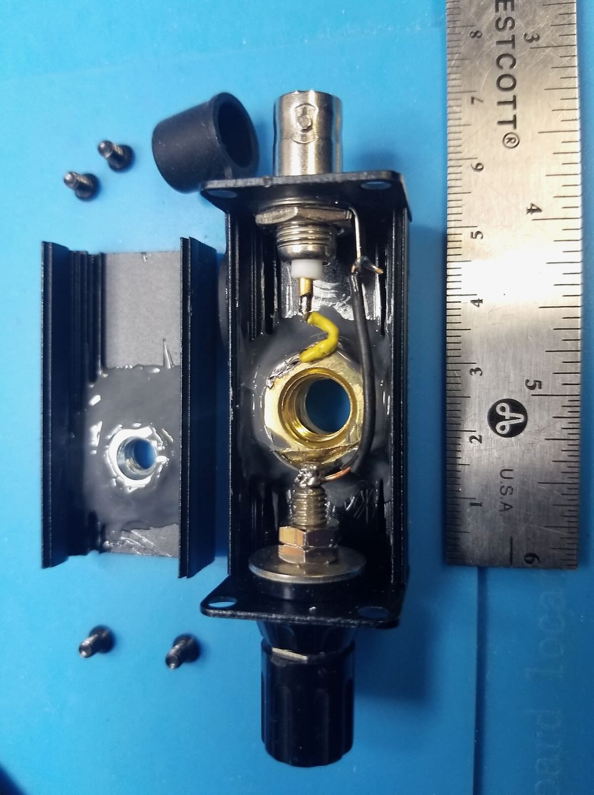
Figure 2 – Antenna mount unclamped from top of monopod. The black plastic fitting (at right, with wedge-shape) fits into slot on platform at top of monopod (at left) and clamps in with cam arm. Large steel screw attaches wedge fitting to antenna mount case. Ruler shows scale of things.
Figure 3 – Antenna mount case (right) unscrewed from camera mount fitting. Steel screw is standard camera mount size (1/4-20 thread size). Black silicone cap keeps dust out of BNC connector. If your camera mount does not have a detachable wedge fitting (like the one on the left), you would simply screw the camera mount screw directly into the bottom of the antenna mount case.
Figure 4 – Top of monopod dissembled to show (clockwise from top): black monopod tube with telescoping whip stored inside (stainless steel with 10 mm brass mounting bolt), antenna mount case, detachable camera mount fitting, and round top plate of monopod. For my monopod, I had to remove one tiny screw and apply gentle torque to break a weak glue joint of this round piece on top of the monopod leg. It remains a snug hand fit (no screw needed).
Figure 5 – Fully assembled whip antenna mount with wiring. Radial (blue wire) with tie-off cord (yellow) at left; RG174 coax (5 m) at right. Whip is only ever screwed in hand-tight. Deploying in the field, I first tie off the monopod to something (park bench, picnic table, fence, tree), then screw the collapsed whip into the antenna mount and clamp mount on top of monopod, then plug in radial and tie the yellow cord off to something (straight out at 2 m height or slope down to ground anchor), and finally connect the coax to the rig. When all in place, I carefully raise the whip (slowly, with two hands to reduce bending forces). Take-down is all in reverse.
Figure 6 – Detail of antenna mount case. Case is 50 mm x 25 mm x 25 mm aluminum clam shell box with square metal end plates. These end plates are screwed in to hold the two halves together. White plastic bushing provides additional lateral support for the whip when it is screwed in. The bushing is glued to outside of case with CA (Krazy) glue.
Figure 7 – Inside of antenna mount case. On left, a ¼-20 steel nut is epoxied to inside of case with strong JB Weld epoxy. In main case, a 10 mm brass nut is epoxied to inside of case with an insulating washer beneath. This brass nut connects to the whip and is “hot”, so must be insulated from the black aluminum case. Yellow wire connects center of BNC to brass nut (soldered). Black wire connects ground side of BNC to radial banana jack. Use plenty of epoxy; there is a lot of force exerted on the steel and brass nuts.
Figure 8 – Detail of inside of case. Note separation of banana jack solder post and edge of 10 mm brass nut. Solder yellow wire to nut before epoxying in nut.
Hope you find this useful. Just use what you have on hand and some ingenuity to make yours!
Many thanks to Drew (W8MHV) who shares the following guest post:
QRP in Thailand
by Drew (W8MHV)
I travel to Southeast Asia each year and usually have a few weeks in Thailand, but this year we planned on a longer stay. My XYL (N8MHV) has family in Thailand and we own a condo in downtown Bangkok. This year I was intent on getting my Thai ham license; I have never previously been licensed there.
You might be surprised to know that Thailand doesn’t make it easy for a casual American visitor to be awarded a ham license, even though the country has a bilateral agreement with the US on licensing.
For starters, you must have a visa for a long stay. A visitor can stay in Thailand for 30 days without a visa, and I have always limited my stay accordingly. But this year we stayed for of two months and getting a visa was necessary. That wasn’t especially difficult once my Thai-speaking wife helped figure out the necessary paperwork. In Thailand my wife’s calls to government offices led to a contact with the Radio Amateur Society of Thailand (RAST). Once I joined the organization, they helped push through the application and award of the license.
The RAST Secretary whose nickname is Top was a very great help. I felt like this was a big achievement as there are fewer than 1,000 ham licensees with HF privileges in a country of about 70-million.
QRP operating from anywhere in Southeast Asia requires great patience. This is because if you operate in a DX location, then everyone you work is DX to you, as by definition there are few if any local stations!
I brought my newly-acquired Elecraft KH1 for on-air use. Its tiny size made it easy to pack for overseas travel. It worked flawlessly, but the built-in whip antenna was far less useful than a 20.5 foot random wire with counterpoise I included in my kit.
Operating the KH1 from my condo.
In my 12th floor condo noise levels were terrible—typically S7, but at the top of the building on the 24th floor there is a garden where the noise levels were a manageable S3. See the photo above.
I also operated from an island in the Gulf of Thailand at a resort and noise levels there were even more quiet, as you would expect. Also, this was a comfortable operating location as the photo shows.
During my stay propagation conditions were poor mostly and I struggled to work any stations. A typical example is my final night in Bangkok I repeatedly called a station in Hong Kong whose signal was about S5, but I never got an answer. It was about the closest station I heard, but the signal path was about the same as the distance between New York City and Caracas, Venezuela.
I have operated from other Asian locations with QRP radios many times and the results have varied, chiefly depending on the kinds of antenna I could erect. Sometimes it has been lonely, other times control of a big pileup has been a challenge.
Finally, a few thoughts about the KH1.
It is an unparalleled performer for its size. It has most features you would want and its ergonomics are good. The weakest point was the paddle set, and since returning, I have replaced them with the KM4CFT aftermarket set. That said, in my travel to Thailand next year, I think I will take a KX2. It offers a few more features at a small increase in packing size.
Many thanks to Sam (WN5C) for sharing the following guest post:
Homebrew in the Field
by Sam (WN5C)
What a week it’s been!
I have the opportunity to spend a month traveling through and camping in the American Southwest (specifically, New Mexico, Arizona, and Colorado) doing archaeological work. And of course, that means the prospect to operate portable at weird times and in lots of places.
I’ve been planning for this trip for a couple of months, about the same length of time that I’ve been trying to achieve my amateur radio dream: to build a complete transceiver. So why not try to do both things at once?
This is just a quick note of my experiences in the first quarter of my trip of taking a homebrew rig into the field.
First off, I have absolutely no background in RF engineering, or electronics at all. But the literature is good and Elmers are priceless (thanks Kenn KA5KXW!). I started small, with kit projects, and then very basic transmitters.
I’ve always appreciated how much satisfaction my father gets by building things by hand, and finally I have a similar hobby. I called the radio I designed the Thunderbird Mk 1 based off the fact that I cut my CW and POTA teeth at Lake Thunderbird State Park in Oklahoma and will probably continue to work there the most. It’s a 6-band (40, 30, 20, 17, 15, 10) CW QRP transceiver with SSB receive.
The receiver is direct conversion and is an amalgamation of VU2ESE’s DC40, KK7B’s Classic 40, and W7EL’s Optimized QRP Transceiver. The VFO is an Arduino/si5351 combo based on the schematics and code written by VK3HN (who has helped me from afar, thanks Paul!). It’s crude, but I use a 6-position rotary switch to manually switch between the band-pass filters.
The transmitter is based on W7ZOI’s Updated Universal QRP Transmitter, married with VK3HN’s Arduino code that acts as the oscillator, keyer, and side tone generator. I get about 3 watts output for 40, 30, 20, a little less for 17 and 15, and about a watt on 10 meters. Like the receiver, I manually switch the low-pass filters.
Here’s a picture of the digital parts (ignore the second Arduino Nano, I thought I would need it but did not), the power board, and the filters. It’s on the bottom:
On top is the main board with the receiver, the transmitter, and T/R switching. Also, you’ll notice the green PCB. I *really* wanted to build NM0S’s Hi-Per-Mite from scratch but I couldn’t get the circuit to run right before my trip so I opted to install one that I built from a kit. It’s a fantastic CW audio filter that I can switch in and out (everyone should have at least one!).
I can switch in a little speaker and added a straight key jack. I printed the box on a 3D printer at the local library. It works great for the shack. In the sun, it’s starting to warp in the heat, so I’ll have to address this, but things still work!
Getting out the door on time with a finished radio was tough! I had finished right before I left on my trip (end of May 2024) and had no time to field test. The best I got was taking the rig to the table in the back yard and firing it up during the WPX contest.
I made amazing DX contacts on all the contest bands I had and called it good. But working superstations isn’t real life, and over the next week I’ve had to MacGyver the radio (rigging a car jump pack, an inverter, and a soldering station together at a picnic table to replace a bad transistor, for example). I think I’ve finally shaken out (literally) all of the loose solder joints and bad grounding. Continue reading Sam’s Thunderbird Mk 1 Takes Flight: A Homebrew Radio Field Report from the American Southwest→
QRP radios, product announcements, reviews, news and more. Low power amateur radio fun!
Please support QRPer by adding us to your whitelist in your ad blocker. Ads are what helps us stay online. All of our ads are ham radio related--no junk, we promise! Thank you!