If you’d like to participate in a contest that balances the playing field between fixed, high-power stations and QRP portable stations, you might take a look at the 2nd annual Portable Operations Challenge.
The POC will take place September 4-5 during three, 4 hour periods. The exchange is very simple: your 4 character Maidenhead Grid Square. You can even combine this event with a scheduled summit or park activation.
This contest even includes prizes for the winners.
The Fox Mike Hotel Portable Operations Challenge is designed to optimize equal operating conditions for portable operating during a contest involving non-portable stations. The scoring allows and encourages regular home-based station operations to take part while offering a handicap-style scoring algorithm to be more equalized for portable stations. The approach is akin to the handicap index in the sport of golf. More difficult courses are scored with a higher slope value, indicating a greater challenge to achieve a normal par score of 72 on that course with a handicap of subtracting strokes for golfers who do not typically shoot as low a score as other golfers. A number of factors go into deriving the slope rating for a golf course but they represent the challenge that the course presents to each participant golfer and the golfer’s capability for playing the course.
The POC aims to make portable operations “on par” with more typical fixed-based operations while preserving the enjoyment of being in a new operating environment. Moreover, fixed-based operators can also easily participate in the action, challenging the handicapped-scoring for portable ops. Can the Super Station contester best the Little Pistol portable operation? If we use a scoring metric that reduces the advantages of fixed stations to that of pure radio sport operating, is there a chance that an efficient portable operator or team can come out ahead of the current winning contest station operators? That’s why this is called the Portable Operations Challenge!
Frank K4FMH
THEORY OF THE CONTEST SCORING FACTORS
Several aspects of fixed (permanent)-station contesting can be stacked in the operator(s) favor when compared to most portable operations. One is the use of greater RF power output. Another is a permanent tower with directional, gain producing beams. A third is that it is easier to have multiple transceivers and operators, allowing for a “per-transmitter production” that yields superior scores. A fourth is the mutual attractiveness for fixed-station ops to work other fixed-station ops and ignore the weaker (especially QRP) signals. The addition of having the full force of Internet communications (when allowed), spotting sources, better ergonomics for operating positions, food/drink conveniences, and climate-controlled shelter all add-up to give “course advantages.”
While some portable operations (an example can be some large Field Day teams) can meet or exceed the advantages to contesting identified above, the vast majority do not.
Our scoring metric equalizes some of these advantages. Four factors are used in scoring each contest operation submission. These are the same regardless of whether it is a single operator or a team of operators, unassisted or assisted through the use of operation spotting. These include:
a. Kilometers-per-watt (KPW). Using the Maidenhead Grid Square, the distance in miles divided by the reported power output in watts for the reporting contest participant.
b. Fixed (permanent) vs Portable operation (favoring portable).
c. Mode of contact: Phone vs. CW vs. Digital (favoring phone over CW over digital)
d. Number of transmitters in use (points X 1/t where t = # transmitters)
The logic underlying this metric is as follows:
The KPW metric will tend to equalize power used as well as antenna gain. The km-per-watt is computed per-contact using the centroid lat-lon of the Maidenhead grid square exchanged during the contact. Favor goes to the greater miles-per-watt which equalizes to some degree the antenna gain, power, and point-to-point propagation conditions. The MPW is the basic contact score. Fixed (permanent) station operators have their resident setup which gives an advantage over portable ops, although a team could replicate a Field Day setting with portable crank-up towers, amps, generators, and so forth. Favor goes to the portable operator. The amount of this multiplier can be adjusted much as a competitive “tuning parameter” in future contests.
All things being equal in a QSO, phone is most challenging, followed by CW and then digital (especially weak signal modes like FT8). Favor goes to phone first, CW second, and digital third.
The more transmitters shape the number of contacts so more transmitters get increasing decrements in the points awarded, regardless of the number of ops. This emphasizes the per-transmitter production rather than just the amount of equipment and number of operators. We are experimenting with what seems appropriate discounts for the number of transmitters in simultaneous so as to render a more equitable competition, favoring sport over equipment.
POC DATES
SEPTEMBER 4-5, 2021
CONTEST OBJECTIVE:
For portable and fixed stations to work as many other portable and fixed stations as possible during the contest
period.
CONTEST PERIOD:
The contest consists of three individual and separate 4-hour periods on September 4 & 5, 2021 UTC.
The sessions are:
Session 1: 0800 – 1159 September 4, 2021 UTC
Session 2: 1600 – 1959 September 4, 2021 UTC
Session 3: 0000 – 0359 September 5, 2021 UTC
Stations may be worked once per band and mode by session for a maximum of 15 contacts between stations per session. Duplicate contacts will be removed without penalty. Scoring will be done by each individual session. Participants may operate one, two or all three sessions. Overall champion will be determined by aggregating scores from the three separate sessions. The Individual with the highest aggregated score will be crowned Grand Champion. The single station with the longest distance in KM per watt will be the Distance Champion.
BANDS:
80, 40, 20, 15 and 10 meters
MODES:
CW, Phone (SSB), and Digital
Digital mode is any data mode that can transmit the required contest exchange. Cross mode contacts are not permitted.
EXCHANGE:
4-character Maidenhead grid square
SCORING:
Total score for the session is the sum of all QSO Values.
I have been a fan of QRP operating since I got licensed in 1983. The sticker in the picture is a joke a good friend who is not into CW or QRP, so I include it in my field pictures.
My interest in ham radio had reached a point I was getting away from the hobby. In 2020, I learned about Parks on the Air (POTA) and Summits on the Air (SOTA). I got hooked on activating parks and summits, and now I mostly do QRP CW, much like Thomas Witherspoon, K4SWL does.
Over the past year, I’ve been refining my antennas and radios in the field. I have different radios and antennas for different reasons, and to just mix it up a bit. Occasionally, I will take my IC-7100 or IC-7300 out into the field with my Bioenno 20aH battery, if I’m not planning to hike or go far from the parking lot, or if the bands are just not cooperating.
Back in November 2020 I had my left knee replaced so I had lots of down time and made an important purchase for field activities – an IC-705. It is fantastic and does everything I want it to do without a lot of wires. I’ve also owned and sold within the past 18 months a Yaesu FT-891 (which I sold when I got the IC-705) and had both the Xiegu G90 and X5105. I would expect one day to get another FT-891 as it has amazing filtering and pulls in weak CW signals better than any radio I’ve owned. The G90 and X5105 are okay, however I was not impressed with the G90 from the start for out in the field. There were just too many wires in order to set up and use with my portable laptop computer if I was taking that along.
The X5105, which I had high expectations for, disappointed me in the fact that storing and using CW memory keying is not user friendly. The nice thing about that radio is, no microphone, no problem, I had some success using the 5105 and got great audio reports.
I’ve been looking ahead to my projected retirement and hopes of through hiking the Appalachian Trail in 2026. Although the IC-705 is an excellent field radio, all mode, VHF/UHF/D-Star/HF/6 meters, I already know for a 7 month hike from Georgia to Maine, it will just be too bulky in my backpack. I have heard really good things about the QCX-mini, however I’m an appliance operator and not good with kit building and soldering.
I saw there are options to purchase an assembled QCX-mini, so I decided to check out a 40 meter radio. It took about 2-1/2 weeks before it arrived at my QTH on Saturday afternoon. I hooked it up to one of my HF antennas in my yard used for my IC-7300 that was resonant on 40 meters. I had to use my Heil headset in order to hear the audio, plugged into the 3.5 mm jack. I used my CWMorse paddle and tuned around the band. I called CQ several times before finally I heard WA0USA in Palm Beach, FL calling CQ. I called him and got a 579 report and he was a solid 599. We chatted for about 10 minutes, and he was running a kW while I was using 5 watts. It felt good to know that I was being heard.
Sunday morning I had time to go activate a local park (K-1418) before some afternoon commitments. I had also recently purchased a link dipole for 20/30/40 meters off eBay from N9SAB. I had tested this antenna out a couple of times last week, so I wanted to pair it with the QCX-mini. I went with little expectations about the little mini, so I also packed my IC 705 just in case I needed it to complete my 10 contacts to have a successful activation. To my surprise, I spotted myself on the POTA page, and in 45 minutes I had a total of 26 QSOs in my HAMRS log! It was amazing and I think I found the perfect combination for true lightweight, portable operations.
I was so impressed with this activation that last night I ordered the 20 meter QCX-mini! These can be ordered from qrp-labs.com and they have a lot of other kits available as well. The kit itself is $55, and I opted to have it assembled ($45) and purchased the enclosure ($20).
This little radio is very user-friendly. I was able to easily access the menus, customize it to my liking, including the paddle, preset frequencies, several stored CW memories, and was on the air calling CQ Saturday evening without seeking out the instructions.
I had mentioned previously about my disappointment with the Xiegu X5105 and not being able to easily store and recall memories. Not a problem at all with this little radio. I enabled the decoder feature just to test it out, and it decodes better than the G90 or X5105, including very weak signals. The size is a fraction of the size of the X5105 and total weight for everything, including the Bioenno 12v 3aH battery is less than 2 pounds and it all stores very nice.
These quick videos were taken this evening before storms hit; that’s why you will hear lawnmowers in the background. I wanted to first show a demo of the receive decoder and how well it decodes even weaker signals:
My biggest complaint about the X5105 was how the memory was next to impossible to use. I do a quick demo how to access a stored message and send it over the air. I also have it set to repeat every 6 seconds:
I did make a couple of changes to the radio setup. I did not like having to use the headset, so I went on Amazon and purchased a mini portable 3 watt mobile phone speaker line-in speaker with 3.5mm audio interface (affiliate link). That cost under $15 and works extremely well. It has a built in charger that plugs into a micro-USB to charge the battery when not in use. I also have a cell phone holder that fits perfectly on my Neewer stand I purchased several months ago for my IC 705, and it sits nice and firm on the table. I may not take that to the field if I’m doing a lot of hiking.
Here are some other details about the QCX-mini from their website:
The Optional enclosure is black anodized extruded aluminium, very sturdy and elegant. The enclosure size is 95 x 63 x 25mm without protrusions. The top and side panels are drilled and cut to match the QCX-mini with laser-etched lettering. The enclosure includes four self-adhesive feet.
Special portable-friendly features:
Small size: 95 x 63 x 25mm enclosure (plus protusions)
Low current consumption (for example 58mA receive current, with 12V supply and display backlight off)
Low weight, 202 grams
Sturdy extruded aluminium enclousre
All-metal BNC short connector, bolted to enclosure
List of features:
Easy to build, two-board design, board with main circuit and connectors, display panel board with LCD; all-controls board-mounted on a press-out sub-board. No wiring, all controls and connectors are board-mounted
Professional quality double-sided, through-hole plated, silk-screen printed PCBs
Choice of single band, 80, 60, 40, 30, 20 or 17m
Approximately 3-5W CW output (depending on supply voltage)
High performance receiver with at least 50dB of unwanted sideband cancellation
200Hz CW filter with no ringing
Si5351A Synthesized VFO with rotary encoder tuning
16 x 2 yellow/green LCD screen
Iambic keyer or straight key option included in the firmware
Simple Digital Signal Processing assisted CW decoder, displayed real-time on-screen
On-screen S-meter
On-screen real time clock (not battery backed up)
Full or semi QSK operation using fast solid-state transmit/receive switching
Frequency presets, VFO A/B Split operation, RIT, configurable CW Offset
Configurable sidetone frequency and volume
Connectors: 2.1mm power barrel connector, 3.5mm keyer jack, 3.5mm stereo earphone jack, 3.5mm stereo jack for PTT, 3.5mm stereo jack for CAT control, BNC RF output
Built-in test signal generator and alignment tools to complete simple set-up adjustments
Built-in test equipment: voltmeter, RF power meter, frequency counter, signal generator
Beacon mode, supporting automatic CW, FSKCW or WSPR operation
GPS interface for reference frequency calibration and time-keeping (for WSPR beacon)
CAT control interface
Optional 50W PA kit
Optional aluminium extruded cut/drilled/laser-etched black anodized enclosure
Just a quick note on the link dipole. It is well made and I had a 1:1 SWR on the CW part of the band, which is perfect. I did put the IC 705 to work when I attempted to work a couple of SSB stations on POTA, and at 7.235 the SWR was only about 1.3:1, so minimal loss. Check out the N9SAB antennas on his eBay site. His shipping is very quick. I took a picture of the balun with the included choke in the package I purchased, and the second picture is the link between the 20 and 40 meters. It works great.
I mentioned my goal about hiking the Appalachian Trail in 2026. I’m sure there will be other multi band mini size radios available by then and I’m hopeful QCX will have one in 5 years for me to use. My goal is to activate summits along the way while taking breaks from the hiking, or at night before calling it an evening. Since I’ll be on the A.T. I’ll also have lots of opportunity to activate POTA as well. Most thru hikers are not hams and they are always concerned about no cell phone coverage. I won’t have that issue and I’m confident I’ll be able to be in touch with other hams throughout the journey.
Thank you once again Tom for allowing me to post on QRPer. I think I finally have a QRP radio that you have not tested or purchased yet. I hope your readers find this short article useful.
73
Scott – KN3A
Scott Lithgow (KN3A) is a regular contributor on QRPer.com. Click here to check out his previous posts.
It’s funny: when I started my POTA journey in earnest during February 2020, I plotted out all of the state parks in the part of western North Carolina where I travel the most.
At the time, POTA had only a wee fraction of the community it does now and many of the parks and game lands were still ATNOs (All-Time New Ones)–parks that had never been activated. Fort Dobbs was still one, in fact, and I had marked it on my POTA game plan spreadsheet.
My mission back then was to rack up unique-to-me parks as I explored the region; in doing so, I ticked off quite a few ATNOs. It was fun!
I focused on parks a little further afield first. This provided me with a sense of adventure and travel during the first round of Covid-19 lockdowns.
At the end of 2020, I realized I had never activated Ft. Dobbs State Historic site which was, ironically, one of the lowest hanging fruit sites around. It’s only, perhaps, 30 minutes from where I travel each week.
I suppose Fort Dobbs has been “out of sight, out of mind” until I saw a tweet from Andrew (N4LAZ) who activated Dobbs on August 6, 2021. I mistakenly assumed that the only spots to set up on site were around the periphery of the parking lot. This time of year, in the middle of the hot and humid summer? I’m less enthusiastic about open parking lot activations.
Andrew mentioned that the site actually has an excellent covered picnic area where he was allowed to perform his activation.
That’s all I needed to know!
Fort Dobbs State Historic Site (K-6839)
On Tuesday, August 10, 2021, I traveled to Fort Dobbs State Historic Site and quickly found the covered picnic area Andrew had mentioned. It was, indeed, ideal for POTA!
As I mentioned in a previous post, I do love rotating out radios I take to the field. Shuffling radios not only helps me remember a radio’s features and menu system, but it helps me understand any advantages one radio might have over another.
One radio I use at the QTH a lot is the Mission RGO One. I reviewed this radio for The Spectrum Monitor magazine, and later posted the review on The SWLing Post. It has been a few months since I posted a field report and video using this rig yet it’s one readers ask about all the time because this is a small production run radio.
Before heading out to Lake Norman State Park on August 9, 2021, I grabbed the Mission RGO One, the Chameleon CHA LEFS sloper, and my 15Ah Bioenno LiFePo4 battery. I knew this combo would serve me well as propagation that day was in the dumps!
Lake Norman State Park (K-2740)
Lake Norman is such an effortless park to activate. They’ve a huge picnic area, large trees (for both antenna support and shade!), and are typically not incredibly busy during the week. I love Lake Norman because they also have a very nice Lake Shore Trail I enjoy hiking post-activation.
That Monday morning, as I drove to the park, it was approaching lunch time and I did worry that some of my favorite picnic spots might be taken, but when I arrived, I was happy to see I pretty much had the place to myself!
Setting up the CHA LEFS sloper antenna takes a couple minutes longer than a standard end fed antenna only because the feed point is elevated and the radiator slopes down from the feed point. Since I typically do activations on my own (with no extra hands to help), I find that a little extra antenna prep equates to a quicker overall deployment.
My procedure for deploying the CHA LEFS
The CHA LEFS sloper
First thing I do is identify a good tree limb at least 45′ or so high and also identify an unobstructed path for the sloping radiator to travel.
Prior to hoisting the antenna, I stretch out the radiator and attach it to a tree or support (using the supplied paracord) in the direction I want the slope to follow.
I then use my arborist throw line to snag the desired tree limb and I connect the end of the throw line directly to the CHA LEFS’ feed point. Chameleon provides Paracord for hoisting the antenna, but the great thing about the arborist throw line is that it’s more than strong enough to handle this job. It saves the extra step of pulling paracord through the tree.
Next, I attach a 50′ length of coax (PL-259s on both ends) and stretch the coax out in the opposite direction of the CHA LEFS radiator. Doing this keeps the antenna from spinning and tangling the radiator and coax as it’s hoisted into the tree.
Finally, I simply pull the throw line and raise the antenna feedpoint to the desired height. Again, I like a height of at least 40-45′, but lower will still work. As I raise the antenna, I do put a little tension on the coax feedline just to keep it from swinging around the throw line or radiator.
Of course, if you have two people, one person can simply stretch the coax as you’re raising the antenna feedpoint which will also keep it from tangling.
That’s all!
In truth, the amount of extra time to deploy the CHA LEFS as opposed to, say, an end-fed half wave is maybe three minutes.
I picked the Mission RGO One because it has an amazingly quiet receiver and handles QRN like a champ. Plus, being a tabletop radio, it also sports a proper speaker, large controls, and up to 50 watts of output power if needed.
Although I’m a QRPer, on days with horrible propagation, I have been known to increase the power beyond 5 watts if operating SSB especially. This year, I set out to validate all of my park and summit activations with 5 watts or less, so at least my first ten contacts at a park will be QRP.
I thought I’d start by calling CQ on the 40 meter band in CW. Within 15 minutes, I snagged the ten contacts needed for a valid POTA activation. I was very pleased with this.
Since I had mobile phone service, I checked the POTA spots and worked AA3K (Park To Park) then moved to the phone portion of the 40 meter band.
During the exchange with AA3K, I did pump the power up to a cloud-scorching 20 watts! A proper rarity for me.
I then worked an additional five contacts in about 8 minutes in SSB. Very satisfying!
QSO Map
Here’s my QSO map of the entire activation. The red polylines represent SSB contact, the green are CW:
I was very pleased with the results especially after reading reports from other activators that same day who really struggled to get their ten.
Video
Of course, I made one of my real-time, real-life, no-edit videos of the entire activation. If you’ve never seen one of my videos before and have a strong dislike of professional, well-polished YouTube channels, you’re in for a treat!
Post-activation–and despite the heat and humidity–I hiked the length of the Lake Shore Trail; roughly six miles. I highly recommend this trail if you can fit it into your schedule.
Thank you!
As always, thank you for reading this report and thank you to those who are supporting the site and channel through Patreon and the Coffee Fund. While certainly not a requirement–my content is always free–I really appreciate the support.
Here’s wishing everyone a little radio fun this week!
With so many great radios in your livery, how do you decide which one to take with you on an activation? I mean, outings other than when you are reviewing a particular radio.
Do you just grab them in a rotation to keep operating features fresh in your mind? Or do the radios have “personalities” that you match to the type of trip you are taking them on?
Thank you for your question, Greg, because I’ll admit, this is a decision I make each and every time I go on an activation run. I’m absolutely spoiled by having access to some of (what I consider) to be the best portable transceivers out there. I’ve acquired the bulk of these in the past four years.
You essentially answered your question for me.
Rotation
The Mission RGO One pairs nicely with a Nacho Salad
I enjoy rotating through my transceivers, ATUs, and antennas because I love trying different pairings. Sometimes, I decide what radio to take on an activation by looking at previous field reports and then pick one I haven’t used recently.
This post reminds me that I need to take the IC-703 Plus out soon.
I love using gear in rotation because, as you suggest, it keeps their operating features fresh in my mind. It’s nice to be actively working stations in the field and not struggle with the rig to find filter adjustments, memory keying, keying speed, mic gain, RF gain, etc. With so many small radios having nested menus, using radios in rotation helps my rig feature “muscle memory.”
Site pairing
With that said, I will ignore rotation if I’m going to a site and know that one model of radio might give me an advantage over another.
If I’m going to a park and plan to do a picnic table activation, for example, any of my radios will work. These tend to be the times I try new antennas and new accessories because I can bring spare gear if something doesn’t work properly.
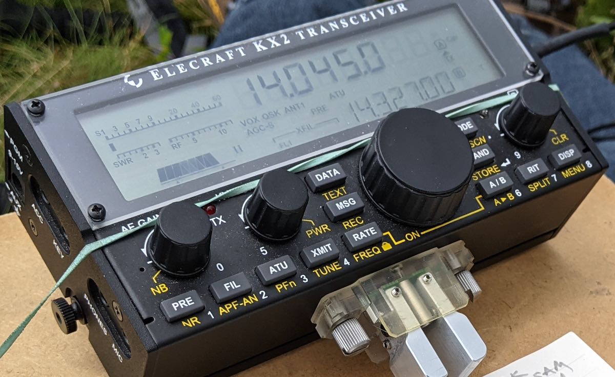
My KX2 often gets picked when I know I might be sitting on the ground for an activation. It allows me to have an entire radio shack on the end of my clipboard.
But, if I’m taking a long hike to my activations site–say for SOTA–I will grab a rig that’s more portable, with more built-in features, and pair it with antennas I know I can deploy on the summit.
Personalities
You’re right, I do believe each radio has a personality and this will sometimes influence my choice. I’ve been known to anthropomorphize my radios and, yes, even name them. Don’t judge me!
Here’s how I would describe the personalities of some of my favorites:
Mountain Topper MTR-3B: Wee, fun, effective, and bare-bones yet nearly custom for CW field activations.
Elecraft KX1: An effective, impressively portable, and reliable CW companion.
Elecraft KX2: The bees knees for a portable HF operator. Always ready-to-go, never intimidated by site conditions, a proper super compact HF Swiss Army Knife.
Discovery TX-500: If Jeep or Land Rover made an HF rig, it would be the TX-500. It’s ready for any weather, packs great performance, and is incredibly fun to operate.
Icom IC-705: All the comforts of a shack-grade, wide range, multi-mode transceiver, packed into a QRP brick.
Yaesu FT-817ND: The Toyota sedan of portable transceivers. Super reliable, rugged, and capable.
Xiegu X5105: An unrefined, competent, and rugged field performer. It’s a lot like one of those dogs that’s so ugly, it’s kind of cute.
Mission RGO One: A low-noise champion that has contest-grade receiver characteristics. I love this performer’s unassuming, simple design.
Elecraft KX3: An HF portable champion. The KX3 will handle the roughest, densest RF environment you can encounter with the optional roofing filter. Possibly the best performing CW rig I own.
So there you go.
I do go through a bit of a selection process prior to each outing and, honestly, it has become part of the fun for me.
Less is more, too
“I might not be a ‘pretty’ radio, Thomas, but I’ve been snagging parks and summits as well as the others!”
With that said, I could easily get away with only owning one or two of the radios listed above. Indeed, for most of my ham radio life, I’ve only owned one or two HF radios.
I actually enjoy being “stuck” with one radio, in fact.
During a normal year, my family will often travel to Canada for the better part of two months. Before leaving, I try to choose only one radio to go with me and it must double as a ham radio transceiver and shortwave listening receiver. It’s fun spending so much time with only one radio and getting to know its features, nuances, and personality.
How about you?
How do you choose radios? Do you feel like your radios have personalities? Do you name your radios? Inquiring minds want to know–please comment!
I saw your recent video post of an activation using the IC-705 and I thought you might appreciate one of my recent related projects. Earlier this year I purchased an Icom IC-705 and because I planned to carry it backpacking for Parks and Summits on the Air, I knew I needed some type of physical protection for it since it would be knocked around a bit on rocks and rough surfaces and during transport. The only cases I could find did not fit my vision; they were either too expensive or too flimsy. So I decided to fabricate my own.
I purchased a 9″ x 18″ sheet of 1/8”, 5052 aluminum. I bent it (with LOTS of effort) in two places which created a “U” channel. The lengths were 4.5″ x 3.5″ x 4.5″. I then cut off the excess and used it to make the side pieces. I then did some research on aluminum brazing which led me to purchase some “AlumiWeld Rods” from Harbor Freight and a canister of MAP gas. I then cut the pieces for the front and sides and brazed them in. You may notice the amateur looking joints on the sides of the armor.
I also wanted to have a mic and key port on the front of the enclosure so as not to be continuously connecting and disconnecting those items directly from the radio and for convenience.
The entire assembly was planned to fit perfectly in the plastic orange ammo box also shown. It is made by a company called Sheffield which is in the U.S.
The radio mounts in the armor via the AMPS pattern screw holes on the bottom. I believe they are 4mm screws… not supplied by Icom. The radio is also electrically connected to the armor via the four screws as well as the shields of the mic and keyer ports.
I recently added the vent holes on the top panel for a less than obvious reason. Although they do serve a dual purpose, my primary reason for adding them was to avoid blocking its GPS reception, but factors of cooling and weight reduction do apply.
73 de Dan (KQ8Q)
This is an absolutely brilliant project, Dan, and to my eye, there’s nothing amateur about it. The coating looks fantastic and I like all of the effort you put into stand-off space to protect the rig and connections. Mounted in that orange box, I think you’ve got an all-weather solution.
Most of my on-air time is in the field. While I enjoy operating from the shack, I’ve discovered I especially enjoy operating in the great outdoors.
Besides being a fan of hiking, camping, and the great outdoors generally, I also am particularly fond of radio field gear. I like portable transceivers, portable antennas, battery packs, and all of the accessories that make field operation efficient and enjoyable.
I appreciate the emergency communications skills I’ve developed in the field, too. Should the need (or opportunity) arise, I now keep a complete field kit packed and ready to go at all times, and can even deploy all of it within just ten minutes. In my early days of ham radio operation, I might have easily spent thirty minutes setting the antenna, alone…especially on Field Day, with folks watching me struggle to untangle wires and cables, followed by the undoubtedly entertaining attempts I made to put a line into a tree to deploy the antenna. But after deploying a variety of antennas hundreds of times now, I find that––while I’m still not perfect––I finally have a bit of skill and the process of tossing up a line is becoming much swifter and smoother.
Confessions of a pack geek
The Red Oxx C-Ruck loaded and ready for the field!
If I’m being honest with myself, I admit: I also simply get a thrill out of kitting out my field packs, as well as organizing and tweaking them over time. Yes, (don’t judge me!) I actually like packing up my field gear.
I think my passion for organizing and packing gear goes back to a former career when I lived in the UK, Germany, and France, and was required to travel throughout Europe frequently. Originally inspired by travel guru Rick Steves, I’ve always appreciated the footloose feeling of having all of my travel gear in one lightweight pack. I don’t like checking in luggage, but love the freedom of grabbing my backpack and skipping the baggage claim carousels. And I also like knowing that, even though my gear is compact, it contains everything I need.
I’ve become something of a “less-is-more” traveller. Two years ago, for example, I traveled for one week using what Frontier Airlines classifies as a “personal carry-on.” My Tom Bihn Stowaway pack, which only measures 14.0″ (w) x 9.4″ (h) x 8.1″ (d), carried everything I needed for a conference, including my own presentation gear.
My Tom Bihn Stowaway personal carry on convertible pack with everything I needed for a one week trip including a conference.
Packing for that trip was great fun as it really challenged me to decide what was essential and what was not. My iPad doubled a computing and presentation device, for example, but I also packed a small flashlight and a mini first aid kit, which I felt were important. Of course, I also carried a small portable Shortwave/AM/FM radio and my Yaesu VX-3R handheld…also vital, as I can’t leave home without radios!
Getting started with a field kit
Putting together a field radio kit is so similar to packing for travel: you must first do an assessment of what you need, starting with the basics––then organize it, pack it, and test it.
In my world, this is a very deep topic. We’re going to break down this topic into two parts.
This article, Part 1, we’ll dive in:
first, going over the obvious components of a basic field radio kit;
second, discussing the benefits of going low-power (QRP) if that appeals
In Part 2, we will:
look at variations of kits based on activity, and finally
review what I consider the “golden rules” of a good field radio kit
The basics of a field radio kit
First, let’s go over the basics of your field kit, considering that that these primary components will dictate your bag, pack, or case size.
A transceiver
The lab599 Discovery TX-500
Since I’m a bit radio obsessed, I have a number of QRP transceivers I like to take to the field. But if you have selected one transceiver you plan to dedicate to field work, or simply have only one transceiver, period, you can build a kit around it (and see my note below about “modular” kits). If budget allows, you might consider buying a radio specifically for field use, so it can always be packed and ready to go.
There are a number of transceivers on the market that are designed with field use in mind. Some are compact, power-stingy CW-only QRP transceivers that might only operate on three ham radio bands, while others are 100-watt general coverage transceivers that even have built-in antenna tuners––there’s a wide range of options.
Look for field-friendly, built-in options like:
CW and voice-memory keying;
SWR and power meter readings;
a battery voltage indicator;
low current consumption;
the ability to lower power to at least one watt;
an internal battery option; and
an internal antenna tuner option
And the more such options are already built into your field rig, obviously, the less separate accessories you’ll need to pack and keep track of in the field, which is a good thing.
The Elecraft KX2 has a built-in ATU, battery pack, and even attachable CW paddles!
Some of my favorite field-ready general-coverage transceivers currently in production are:
The Elecraft KX2 A full-featured, inclusive, and compact 80-10 meter transceiver that’s truly a “Swiss-army knife” of field operation (see November 2016 TSM review)
The Elecraft KX3 Benchmark performance, wide array of features, and compact design
The lab599 Discovery TX-500 Military-grade engineering, weatherproof, spectrum display, and benchmark current consumption for a general-coverage radio (see October 2020 TSM review)
Mission RGO One Top-notch performance, 50-watts out, and excellent audio (see November 2020 TSM review)
The Yaesu FT-817/818 Rugged chassis, 160-6 meters, VHF and UHF multi-mode, both BNC and PL-259 antenna inputs
The Xiegu X5105 Affordable, 160-6 meters, 5 watts output, built-in ATU, and built in rechargeable batttey
The Xiegu G90 Affordable, relatively compact rig with built-in ATU, color screen with spectrum/watefall, good audio, and 20 watts of output power (see August 2020 TSM review)
The Icom IC-705 Benchmark performance, a multitude of features, exchangeable battery packs, 160-6 meters, VHF and UHF multi-mode, D-Star, GPS, WiFi, Bluetooth (see February 2021 TSM review)
The Yaesu FT-891: Affordable relatively compact radio with detachable faceplate, 100 watts output, and excellent audio (see November 2017 TSM review)
An important side note for field contests: if you plan to use a field transceiver in an event like the ARRL Field Day and/or another popular radio contest, make sure you choose a transceiver that can handle tightly spaced signals in an RF-dense environment. This is not the time to pull out a lower-end radio with poor receiver specifications. Use Rob Sherwood’s receiver test data table as a guide.
An antenna––and a means to deploy/support it
The CHA LEFS sloper
This particular topic, alone, might warrant a three-part series of articles. So, to keep the scope of this article realistic, let’s just say that you should build or buy an antenna that can comfortably handle the wattage you’re pushing into itin all the modes that you operate, considering that some 100-watt SSB-rated antennas might melt or arc if you run 100 watts CW or FT8.
I would suggest you consider having at least one resonant antenna, like an end-fed half-wave (EFHW) that might cover 40 and 20 meters without the need of an antenna tuner to match the antenna impedance to your rig.
Some of my favorite portable antenna systems?
I’m a big fan of Chameleon Antennafor their ease of deployment and benchmark build quality. Their prices range from $145 for the Emcomm III random wire, to $550 for their MPAS 2.0 vertical antenna system. These prices are near the top of the market, but Chameleon antennas are all machined and produced in the US and the quality is second to none. These are antennas you might well pass along to the next generation, meaning, really heirloom-worthy kit!
The PackTenna 9:1 UNUN
PackTennas, likewise, are pricey for such a compact product, but they are also beautifully engineered, lightweight, and designed for heavy field use. PackTenna produces an EFHW, 9:1 UNUN random wire, and linked dipole models. They’re some of the most compact field antennas on the market that can still handle as much as 100 watts of power output.
My Wolf River Coils “TIA” vertical antenna
Wolf River Coils verticals are affordable, compact, and resonant––thus an ATU isn’t needed. It will take some time to learn how to adjust the coil during frequency changes, but they work amazingly well. I have the WRC Take It Along (TIA). Their antennas are designed to handle 100 watts SSB, 50 watts CW, or 20 watts digital.
The EFT Trail-Friendly
Vibroplexsells a number of compact field portable antennas and is the manufacturer of Par End Fedz offerings. I’m very fond of the EFT Trail-Friendly and the EFT-MTR.
The MFJ-1984LP EFHW packs a lot of performance for the price
MFJ Enterprisesalso has a few portable antennas in their catalog, and it’s very difficult to beat the price and performance of their antenna gear. I have their $50 EFHW antenna (the MFJ-1982LP) and love it.
The Elecraft AX1 attaches directly to the BNC port on the KX3 and KX2.
I’ve also had tremendous fun with the uber-compact Elecraft AX1 antenna. Unquestionably, it’s the most compact and quickest-to-deploy antenna I own. It’s designed to pair with the Elecraft KX2 and KX3 using the optional internal antenna tuner.
There are a number of other antenna manufacturers who cater to portable operators. For example––although I’ve not yet had the opportunity of testing their antennas––SOTAbeams is highly regarded among SOTA enthusiasts.
Short on cash? No worries; you can build your own! In fact, until 2016, I had never purchased a field antenna; I built all my own. EFHW antennas and random-wire antennas are no more than a carefully-wound coil, a female antenna connector, an enclosure or mounting plate, and some wire. Some of the most active field operators I know homebrew all of their antennas. It’s easy, affordable, and fun!
Make sure you choose a battery that is sized appropriately for your transceiver power output. I will say that I’m a huge fan of LiFePo4 rechargeable batteries for their voltage range, lightweight design, and longevity. Being primarily a QRPer, I typically use 3 to 4.5 amp hour batteries as they’ll carry me through as many as three or four activations without needing to be recharged. For longer field deployments, or when I’m powering my 100W KXPA100 amplifier, I’ll use my 15 aH Bioenno LiFePo4 pack.
I use my 15Ah Bioenno LiFePo4 pack for QRO transceivers
It should go without saying that you need to pack these, but I have gone to the field with operators who forgot their key or mic and asked if I had a spare.
Keys are fairly universal, but keep in mind legacy transceivers often want a ¼” plug while newer rigs typically accept an ⅛” plug. Microphones, however, vary in port type and pin configuration based on the manufacturer and model. You could damage your mic or rig if you plug in a multi-pin mic that was designed for a different transceiver. Most mics that use a ⅛” plug are universal. Still, check before you plug it in if using an after-market or non-OEM mic.
Of course, choose a key, microphone, or boom headset that’s compact and rugged so that’ll be easy to pack and will stand the test of time.
I also always pack a set of inexpensive in-ear earphones. These can dramatically help with weak-signal interpretation.
Also, if you plan to operate a digital mode, you’ll likely need some sort of computing device. Even though I rarely operate digital modes in the field, I often pack my Microsoft Surface Go tablet in case I change my mind.
My Microsoft Surface Go tablet
In addition, I like logging directly to N3FJP’s Amateur Contact Log application directly in the field to save time submitting my logs later. Soon, I’ll be using the new HAMRS field log on my iPhone.
Speaking of logging…
A means of logging
I like compact notepads like Muji and Rite In The Rain for field use.
As simple as it is, it’s very important to take at least some paper and a pencil for logging your contacts. I like using small, pocket-sized Muji notebooks (affiliate link) for logging, and if the weather is even a little questionable, I’m a huge fan of getting my contacts down in Rite In The Rain mini notebooks (affiliate link) or notepads using a good old-fashioned pencil.
I like logging to paper and sometimes simultaneously logging to my Microsoft Surface Go. I have completed phone-only field activations where I only logged to my Surface Go tablet: in those cases, I snap a photo of my N3FJP call log, just in case something happens to my tablet between the field and the shack! Having endured enough technology failures, it gives me peace of mind to have at least one other backup.
Keep in mind that when you’re activating a park or summit, the folks calling you are relying on you to submit your logs to the appropriate programs so that they can get credit for working you. Many times, this might also help their awards for a state, county, or grid square. Always submit your logs after an activation even if you didn’t make enough contacts to validate the activation (POTA requires 10 contacts, SOTA requires 4 logged). It helps other folks out.
A pack or case
If you have a field radio kit, you’re going to need a means to organize and contain it for transport. There are at least three types of systems used for field kits.
A backpack or soft-sided case
My GoRuck BulletRuck is a brilliant SOTA pack
Since I enjoy the option of hiking with my radio gear, I love using backpacks. Although I’ll speak to this more next month in “Part 2,”, I choose quality packs that have at least one waterproof compartment and are comfortable to carry on long hikes. I also try to look for packs with Molle or some sort of external strapping so that I can attach portable antenna masts or even my hiking poles to the exterior of the pack.
A waterproof case or flight case
Ruggedized, weatherproof cases come in all sizes. This Pelican 1060 can house my entire KX1 radio kit.
Many field operators who want extra protection for their gear––especially when they don’t plan to hike or carry their gear long distances to the operating site––like hard-sided cases. I have built field radio kits in waterproof Pelican cases and appreciate knowing that I could drop my kit in a whitewater river, and it would likely survive the adventure unscathed. If you are one of these operators, look for quality watertight cases from brands like Pelican and Nanuk with interiors lined in pick foam padding that allows you to perfectly accommodate and safely protect your radio and accessories.
Portable ready-to-deploy cases
Although this option is almost outside the scope of this article, many emergency communications enthusiasts love having their gear loaded in rugged, portable––often rack-mounted and hard-sided––cases that they can simply open, hook to an antenna, and get right on the air. These systems are often the heaviest, least “portable,” and less suited for long distance hikes, but they’re often completely self-contained, with all of the components, including the power, hooked up and ready to go on a moment’s notice. While a system like this would be impractical for many Summits On The Air sites, it could be ideal for a park or island activation where you’re never that far from your vehicle.
Optional: Antenna cable
An ABR Industries RG-316 cable assembly
This doesn’t sound like an option, but it’s true. I’ve often operated my Elecraft KX3, KX2, and KX1 without a feedline at all: I simply attached two wires to a BNC binding post, and connected that to the radio. It makes for a super-compact setup.
Even an 8-12 foot feedline can make it easier to configure your operating position in the field. If you want to keep the feedline as low-profile as possible, especially if you’re operating QRP, consider investing in a quality RG-316 feedline terminated with the connector that fits your radio and antenna.
Optional: Antenna Tuner/Transmatch
A portable ATU with RF-sensing like the Elecraft T1 will give you an amazing amount of frequency agility. I’ve been known to use the T1 to tune my CHA Emcomm III random wire antenna on 160 meters..
Again, this topic could easily warrant a multi-part series of articles, but I’ll sum this one up in a nutshell: while I love (and even prefer) using resonant antennas that require no antenna tuner, I almost always carry a radio with a built-in ATU or an external portable ATU like the Elecraft T1 or ZM-2.
Why? Because an ATU will give you a certain amount of frequency agility or freedom. If I’m using an antenna that’s resonant on 40, 20, and 10 meters, but there’s a contest that day and the bands are incredibly crowded, I might use the ATU to find a match on 30 meters or 17 meters, thus finding a little refuge and space to operate. Also, sometimes antenna deployments aren’t ideal––due, for example, to site limitations such as dense vegetation that may alter the antenna deployment and thus its resonance. An ATU can at least keep your transceiver happy with the SWR when your resonant antenna might not be perfectly resonant.
But the main reason I carry it? A portable ATU gives you operational flexibility.
QRP or QRO?
I have operated QRO in the field with my KXPA100 amplifier on Field Day.
Its good to keep in mind that many of the station accessories listed above need to be matched to the output power of your transceiver and modes you use.
Many ham radio friendships have been placed in jeopardy over the question of either using QRP (low power) or QRO (high power) for field operations. This is a shame. Some operators have very strong opinions, but the truth is, there is no right or wrong answer.
In the spirit of full disclosure, I operate 97% of the time at QRP power levels––in my world, this means five watts or less. Personally, I enjoy the challenge of low-power operating. But I also appreciate the portability QRP gear offers.
The wee Mountain Topper MTR-3B
Speaking pragmatically––and this fact really isn’t open to debate––QRP and lower-power transceivers and accessories tend to be more efficient, more compact, and lighter than their higher-power siblings.
Most of my QRP transceivers weigh anywhere from two to five times less than their 100-watt equivalents. If you’re operating mobile (from a vehicle or camper/caravan, for example), an eight to twelve pound difference might not be a big deal. But the moment you’re hiking several miles to a mountain summit, weight becomes an important factor.
QRP transceivers have modest power requirements: everything from battery, to antenna, and even to tuners, are smaller, lighter, and more compact.
When operating QRP, you don’t have to worry as much about RF coming back to the radio from, say, an end-fed antenna. If I’m pushing over 20 watts into an end-fed half wave or end-fed random wire, I’ll likely want an in-line RF choke to keep some of that energy from affecting my transceiver or giving me an RF “tingle” when I touch the radio chassis or my key. Too much RF coming back to the transceiver can also affect things like electronic CW keying. But at five watts? I don’t worry. This is almost a non-issue, unless your transceiver happens to be very RF-sensitive indeed.
And even though I’m predominantly a QRPer, I definitely do pack radios like the 50-watt Mission RGO One and occasionally my Elecraft KX3 and KXPA100 100-watt amplifier, especially for an event like Field Day where my club is operating at higher power. I simply size up my gear appropriately. Again, this is especially important with your antenna, feed line, ATU, and battery selections.
If you primarily activate parks and are never far from your vehicle, it’s quite easy to accommodate a 100 watt transceiver like an FT-891, for example. Of course, if you wish to operate low-power and save your battery, simply turn down the output power. If you plan to hike a lot with your gear, then get your mind around QRP!
Stay tuned for Part 2!
In Part 2 we’ll dig into some of the details, looking at different approaches to field radio kits and some guidance and suggestions based on my real-life experience (read: operating mistakes).
Two weeks ago, my buddy Monty and I went on a camping trip near Mount Pisgah off of the Blue Ridge Parkway. It was amazing.
Monty is one of my best friends and like a brother to me. We were roommates during my undergraduate years at Western Carolina University. In those days, we were both into mountain biking, hiking, trail running, backpacking, and camping. WCU was the perfect launching point for all of those activities.
These days, we both still do hiking and a little mountain biking, but at–what we might generously call–a more “relaxed” pace.
Although Monty’s family also live in western North Carolina and we keep in touch pretty regularly, we hadn’t seen each other in person for years, so we knew a camping trip would sort all of that out and give us a chance to reconnect while disconnecting from our busy schedules.
Mount Pisgah
You can’t see it in the photo, but my 25 year old four person dome tent about pushed Monty’s two person dome tent off of the camping pad! And, yes, I brought a butane torch to light the campfire–not exactly bushcraft.
We chose Mount Pisgah campground off of the Blue Ridge parkway for a few reasons: it’s roughly halfway between our homes, it’s at a high altitude which equates to cooler nights during the hottest part of the summer, and–you guessed it–it’s on no less than two POTA sites and close to a number of SOTA summits as well!
Another fun fact about the Mount Pisgah campground? It’s also black bear habitat. I believe I mentioned that when I activated Mount Pisgah earlier this summer, I spotted a number of bears in this area. But hey! Check out the park’s bear traps:
And to be honest? My QTH is also just as much in black bear territory, so this isn’t exactly unfamiliar.
Richland Balsam (W4C/WM-003)
I was up earlier than Monty, so I brewed some coffee, read a bit of my book, and fit in a little early morning POTA!
The weather was ideal on the morning of Monday, August 2, 2021.
Monty actually mentioned in advance that he’d like to accompany me on a SOTA activation or two. He’s an engineer at WCU and I’ve been nudging him for years to get his ham ticket, so how in the world could I pass up a little SOTA/POTA proselytizing?
While Monty cooked up some breakfast burritos, we hatched a plan to activate Richland Balsam first.
Richland Balsam is a very accessible 6,410′ (1954M) summit and is actually the highest peak on the entire Blue Ridge Parkway.
Richland Balsam is a great “beginners” SOTA summit because the loop trail is only 1.5 miles long, well-marked, doesn’t require an experienced hiker, and passes through a spruce-fir forest which not only provides shade, but also ample trees for wire antennas. The trailhead is easy to find as well; it’s at the north end of the Haywood/Jackson overlook parking area.
Only one word of caution: being such an accessible loop trail right there on the Blue Ridge Parkway, it can get very busy during the summer and fall–in fact, you might struggle to find a spot to park. Monty and I arrived early enough that there were only a handful of cars parked at the overlook.
Richland Balsam reminds me of some of the trails in/around Mount Mitchell: lots of ferns, mosses, and and the smell of spruce-fir. Bliss!
On The Air
I’d forgotten that there are actually a couple of benches on the summit of Richland Balsam which is a proper luxury for any SOTA activator!
Monty had no issue at all setting up the Chameleon MPAS Lite vertical on his own as I prepared my clipboard, Elecraft KX2, and log book.
I actually had decent mobile phone service on the summit, so spotting myself was quite easy via the SOTA Goat app. Of course, I assumed I might not have access to spot myself, so I did schedule the activation before leaving the campsite on both the SOTA and POTA platforms knowing both would auto-spot me from the Reverse Beacon Network (RBN).
I started calling CQ on 20 meters CW and my first contact was fellow POTA activator Steve (KC5F) who was, no doubt, working me via ground wave from his home. Always good to have Steve in the logs.
In thirteen minutes, I worked nine stations on 20 meters–lots of familiar calls. I actually validated the SOTA activation (logging four contacts) in no less than five minutes!
I then moved to 17 meters where I worked K6MW in Washington state.
Finally, I moved down to the 40 meter band in hopes of picking up Mike (K8RAT)–success!–and also worked good ole’ Bill (WB1LLY) in Georgia.
Here’s my full log sheet:
Near the end of the activation (you might note this in the video), Monty and I hear a loud animal noise in the forest–very likely a black bear making itself known. We took that as a cue to pack up and move on.
Video
Here’s my real-time, real-life, no-edit video of the entire activation from start to finish. If you’ve been seeking a cure for insomnia, you’ve found it:
After leaving Richland Balsam, we decided to also take in W4C/CM-005 (Black Balsam Knob) which is another 10 point summit on the Blue Ridge Parkway. I tried making a video of this activation, but for some reason the camera shut down after nine minutes. I’m uncertain yet if I’ll publish that video with a post. We’ll see! It, too, was a fun activation.
After Black Balsam, Monty and I prepared a late lunch back at the campsite and decided that there was still enough of the day left to take in the Mount Pisgah summit trail. Frankly, it was simply too tempting! There was a trail not even 25 feet from our tents which lead us to the Mount Pisgah trailhead. Since I had already activated Mount Pisgah only recently, I didn’t take radio gear this time.
Turk’s-cap lilies were in bloom along the Mount Pisgah trail.
Funny, but we both underestimated the hike from our campsite to the Mount Pisgah trailhead. In my head, I assumed it was perhaps half a mile or so. Turns out, it was more like 1.5 miles one way!
The Mount Pisgah tower
Combined with the actual Mount Pisgah trail, it made for a decent amount of hiking. I believe we left the campsite around 16:00 local and were back by 19:00 or so.
That Monday turned out to be a day full of hiking, radio, and hanging with Monty. It was amazing fun.
Thank you
As always, thank you for reading this report and thank you to those who are supporting the site and channel through Patreon and the Coffee Fund. While certainly not a requirement–my content is always free–I really appreciate the support.
Here’s wishing everyone good health and maybe even a little outdoor radio fun this week!
A few weeks ago–on July 12, 2021–I popped by Lake James State Park to do a quick activation with the Icom IC-705. It had been a while since I’d used the ‘705 in the field and the little rig was begging to go outdoors.
Here’s the funny part: I completely forgot about that activation! Two days ago, while browsing my photo archive, I noticed the video I made of the activation and, of course, the memory came flooding back.
In my defense, it has been a crazy summer and the weeks/days seem to all blend together in my head.
Thing is, this activation was memorable for a bad reason: QRM (human-made radio noise). It was also memorable for some of the folks I worked on the air.
Lake James State Park (K-2739)
I arrived at Lake James and was a bit surprised to practically have the place to myself.
I found a picnic table with a view of the water, deployed my speaker wire antenna, and set up the IC-705. As with all of my activations, I was only running 5 watts.
I attached the speaker wire antenna’s BNC binding post adapter directly to the mAT-705 Plus ATU.
Propagation was–you guessed it–forecast as very poor.
It felt that way when I hopped on 40 meters at first as the band was pretty quiet..
Still, I managed to log 5 contacts on 40 meters (two in SSB, three in CW) before moving up to 20 meters which served me well.
I worked a total of eight stations in nine minutes on 20 meters.
QRM
Check out the noise level on the waterfall display!
If you watch the video, you’ll hear how nasty the QRM was at times.
I keep forgetting that there’s a source of intermittent radio interference at the Lake James visitors center. The spot where I set up the station was only 25 meters or so from that building. I believe the center was responsible for the QRM I first experienced during the activation. Whatever the device is generating the QRM, it doesn’t last for long periods of time–it cycles.
The second batch of QRM was emanating from a small boat that pulled up to the dock in front of my site. It was nasty and completely wiped out the 20 meter band. When the owners turned off the boat and stepped onto the dock, the noise stopped completely. Later, when they got back into the boat, the noise started again. I have to assume it was something in their motor causing the QRM. I suspect they may have been using a DC trolling motor.
Memorable contacts
POTA activations often feel like a gathering of friends. I often see many of the same callsigns in my logs and it’s a lot of fun working them each time.
Also, it’s a lot of fun to work stations further afield. At Lake James, I was very pleased to work NK7L in Washington State, IK4IDF in Italy, and HA9RE in Hungary. My back of the envelope calculations tell me that I was pushing 1,000 miles per watt when I worked Elemer (HA9RE). To be clear, all of the work was done on his end as he has some world-class ears; just check out his QRZ page!
For some reason when I logged HA9RE, I copied VA4RE. I’m not sure why, but after packing up it hit me that I had logged him incorrectly (funny how brains work!). I reviewed the video on-site and confirmed it was indeed HA9RE.
Here’s my QSO Map:
I was also very pleased to finally work Dave Benson (K1SWL). He’s very well-known in QRP circles for his amazing Small Wonder Labs kits. Dave’s a great guy and, of course, loves playing radio in the field.
Video
Here’s my real-time, real-life, unedited video of the entire activation. Apologies in advance as I really needed a wind screen over my microphone that day–I had the mic and camera a little too close.
Loop next time!
The next time I hit Lake James, I plan to deploy a Chameleon loop antenna. I think it will have a significant impact on the QRM levels at that particular part of the park. Of course, I could easily move further away from the noise source (that’s the easiest solution) but I’d like to see how effectively a loop might mitigate the QRM. That and it’s been years since I last used a compact mag loop antenna in the field.
Thank you
Again, thank you for reading this report and thank you to those who are supporting the site and channel through Patreon and the Coffee Fund. While certainly not a requirement–never feel an obligation to do so (especially if you’re investing in your first station, for example)–I really appreciate the support.
Here’s wishing you some outdoor radio fun in the near future!
Many thanks to Pete (WB9FLW) who shares a reminder that the QSO Today Ham Radio Expo is this weekend.
I missed the last QSO Today Expo and heard that there were numerous technical glitches. Eric Guth (4Z1UG) has repeatedly described that experience as one of the most stressful in his life. He is making sure that this Expo will run smoothly by keeping all of the presentations and experience on the same platform. Eric is an amazing fellow and has gathered an outstanding group of speakers (over 90, I believe) and has made it so that if you can’t attend live, you can watch the presentations, on demand, for 30 days. Here are a few details from the QSO Today Virtual Ham Radio Expo site:
QSO Today Virtual Ham Expo
Opens: August 14th, 00:01:00 UTC or August 13th, 5:01 PM PDT
Full Registration is $10.00 US – includes full access to the Expo, including presentations, 12 subject video lounges, and to the 30 day on demand period.
Full registration will increase to $12.50 at the door when the Expo opens.
Free Registration is limited to lobbies, exhibition hall, exhibitor booths, and prizes offered by exhibitors. If you already have a free ticket, you can upgrade with the button below.
Connecting an international community through low-power field radio adventures.
Please support QRPer by adding us to your whitelist in your ad blocker. Ads are what helps us stay online. All of our ads are ham radio related--no junk, we promise! Thank you!