Jonathan KM4CFT reached out to me recently to inquire if I was interested in trying his CFT1 QRP transceiver. The inquiry both surprised and delighted me as I’ve never had such an opportunity.
I nearly said no because I am no antenna expert and, as this rig has no internal antenna tuner, I’d need to learn more about antennas, SWR, and resonance.
My limited antenna experience dates back to when I first entered the hobby. I had ZERO antennas and no idea where to start. An acquaintance suggested I make a home-brew linked dipole and gave me a few pointers in doing so. I vividly remember limping through learning how to trim an antenna. That project taught me that I want as low a SWR as possible and to cut the antenna for the portion of the band on which I want to operate.
homebrew linked dipole
Those of you who read my articles here on QRPer know that I use an Elecraft KX2 for my field operations. I’m very happy with this radio and love that it has an internal antenna tuner. But the CTF1 does not. Here is where my hesitation and trepidation at trying this unit entered the picture. I figured the antennas I use on a regular basis might not play nice with the CFT1 and hence my reluctance to say “yes” to this opportunity.
“Craig”, my KX2
But this is ham radio, right? In ham radio, we relish challenges because they are opportunities to learn. This was my opportunity to learn not only about antennas in general but also to be more thoughtful as to how I deploy them in the field. This was an opportunity for growth.
I dug out the RigExpert Stick antenna analyzer I purchased nearly three years ago and tested each of the antennas I currently have, just for jollies. I understand that many factors impact SWR – height of the antenna, coax length, proximity of other objects, etc. For the purpose of this exercise, I just wanted a ball park idea as to what antennas I could or could not use with this rig without a tuner.
I found both the home-brew linked dipole and the Chelegance MC-750 would work fine. Out were the EFRW and AX1. As I’d been hankering for an EFHW in my kit, I purchased the Sparkplug EFHW and trimmed it. These kinds of projects intimidate me because I do not have much experience with them; however, one cannot learn what one does not attempt.
I used the CFT1 on three activations: April 25th at the Savannah National Wildlife Refuge (NWR) (US-0522) with the Chelegance MC-750, April 30th at the refuge again but this time with the Sparkplug EFHW, and Thursday, May 1st at George L. Smith State Park (US-2179) with the Chelegance again.
It was a warm day at the refuge on April 25th. I selected an open area in which I had set up in the past. There were wild blackberries growing directly under the oaks in the shade. The view was lovely and, when not engaged with the activation, the red-wing blackbirds, coots, and other birds kept me entertained. Unfortunately for me, the sun moved out behind the oak trees not long after I arrived and I soon called QRT to avoid being baked.
the field in which I set upwild blackberriescooter out sunning itselfwater lillies in the impoundmentswhat is not to love about that view!?
I was pleased with the QSO map for this activation – 27 contacts on 40, 20, and 17 meters over the course of an hour and a half.
QSO Map for Savannah NWR 4-25-2025 Source: qsomap.com
My second experience with the CFT1 was on April 30th, again at the Savannah NWR, however, this time using the Sparkplug EFHW. I found a different spot, one I passed up before but was usable today as it was freshly mowed. There were wonderful, tall oak trees at this location which afforded shade and high, unencumbered branches for installing an antenna aloft. Continue reading The POTA Babe Tries the CFT1→
If you’ve been a QRPer.com reader or subscriber to my YouTube channel for long, you’ll know I’m quite the fan of super-compact, low-profile antennas like the Elecraft AX1 and AX2.
Although AX antennas are certainly a compromise in terms of performance, I find them surprisingly effective for on-the-air programs like SOTA, POTA, and WWFF. While they’re not high-gain, they’re also far from the “dummy load” some make them out to be. In fact, the best DX I’ve ever worked in the field was with my Elecraft AX2 and just 5 watts of power—check out the field report.
It covers 30 through 10 meters and uses a 4-position band selector plug, which I personally find more rugged than the AX1’s band switch. Like its siblings, the AX3 is designed to pair with an ATU, but unlike the AX1/AX2, it doesn’t need to physically mount to the transceiver—so it’s compatible with virtually any rig and tuner combo. The AX3 also supports up to 30 watts.
Despite the added versatility, the AX3 still packs incredibly small: the whip, base, and tripod legs collapse to just 6 inches, yet the whip extends to 45 inches in the field. The side-mounted BNC connector avoids awkward cable bends or adapters.
In the spirit of full disclosure, I’m in the testing group for the Elecraft KH1 and, as such, I was aware the new AX3 was on the horizon, but I had not yet tested it in the field until I ordered one and it was delivered on Tuesday, April 29, 2025.
From Unboxing to Activation
Since Hurricane Helene wiped out our local post office, my buddy Vlado (N3CZ) has kindly allowed me to have parcels delivered to his house. When he told me that “a small box” had arrived from Elecraft, I knew exactly what it was.
I had an errand in town that afternoon, so I swung by Vlado’s, picked up the package, and then stopped at the Blue Ridge Parkway Folk Art Center to perform the AX3’s debut activation.
Of course, I packed my Elecraft KX2, thinking it would only be right to pair the AX3 with an Elecraft radio for its first outing!
In my activation video (below), you’ll see that assembling the AX3 was incredibly simple right out of the box. I ordered the full AX3 package, which includes the antenna, mini banana plug, counterpoise wire, tripod legs, BNC-to-BNC cable assembly, and a small nylon storage bag.
I attached the tripod legs, screwed on the whip antenna, clipped the counterpoise to the ground lug, and connected the BNC cable. In less than a minute, the antenna was fully deployed and ready to go!
Gear
Note: All Amazon, CW Morse, ABR, Chelegance, Spooltenna, eBay, and Radioddity links are affiliate links that support QRPer.com at no cost to you.
Glenn W4YES and I headed to Camden, SC the first week of April for some much needed rest and relaxation. Usually when I travel, I schedule a POTA activation or two. However, this trip I decided to try something new – getting on the air QRP at our Airbnb.
Camden is the oldest inland community in South Carolina. According to the town’s website, the earliest permanent settlers arrived in 1750. They experienced a crushing defeat during the Revolutionary War when the Patriots were defeated in the Battle of Camden. After the Civil War, the town “evolved into a tourist mecca for Northeners and Midwesterners seeking a warmer winter climate.” Those tourists brought money and an equine culture developed around racing and polo.
Our first day in Camden, we visited the Revolutionary War Museum. Though small in size, the museum’s exhibits are of excellent quality. They do a great job explaining who lived in the area, the quandary they faced as to whether to be a Loyalist or Patriot (it wasn’t as easy a choice as it might appear), and battles fought there.
Our second day, we explored the National Steeplechase Museum. This museum explores the history of steeplechasing and the personalities involved – owners, trainers, jockeys as well as those who care for the horses. The museum pays homage to Marion duPont Scott who developed the Springdale Race Course where the museum is located. This race course hosts two prominent annual competitions – the Carolina Cup and the Colonial Cup.
National Steeplechase Museum
an old scale used to weigh jockeystrophy room
We also spent some time driving through and walking in the historic neighborhoods of the city. The weather was gorgeous! Everywhere we looked, there were flowers – azaleas, wisteria, viburnum, and dogwoods (including the pink variety we do not see in Savannah).
a dogwood in full splendorazaleas at the corner of a homeviburnumpink dogwood
After exploring the area, it was time to explore the airwaves QRP at our Airbnb. To do this, I brought Craig, my KX2, and a home-brew linked dipole antenna. This is an antenna I built three years ago, when I first got into ham radio. At that time, I had no home station but wanted to get on the air portable for POTA. Despite knowing almost nothing about antennas, I built a usable dipole that became my main POTA antenna for quite a while.
the homebrew linked dipole (photo from GA State Parks on the Air event)
Why did I bring this antenna to Camden? I have the opportunity this month to try the CFT1, a QRP transceiver, by Jonathan KM4CFT. Because the rig does not have an internal antenna tuner, I am reacquainting myself with the subject of resonance and why it matters in antennas.
I set up a home-brew linked dipole Wednesday evening under some trees in a space between the Airbnb and a small lake on the property. The antenna was roughly 20 feet in the air.
the lake from the Airbnb2nd location for antenna by lake
My RigExpert Stick analyzer gave me 2.1 at 7.040 –
Thinking I could do better, I moved the antenna (a real pain to do with a dipole) to a different tree with a limb 30 feet high. (Frankly, Glenn and I were amazed I could snag that limb.) This setup generated better a SWR reading – 1.61 at 7.040 MHz.
Now the true test – how well would I be heard?
the bench at which I operated Wednesday eveningRBN picking me up Wednesday evening
CW nets are a great place to get on-the-air experience with morse code. It was my code buddy Caryn KD2GUT who first introduced me to the OMIK net. I found those who participate in this CW net to be welcoming and accepting of CW operators of all levels of proficiency. Over the past several years, the ops in this net have watched my skills grow and become friends.
Dennis NT4U and Steve W0SJS split net control station (NCS) duties. This evening, it was Dennis’ turn as NCS. As he is located in northern Georgia, I figured he would hear my QRP signal. He did and checked me into the net with a RST of 589. The icing on the cake was that I heard a station he was unable to hear – Charles AI4OT in Virginia – due to the S9 noise at Dennis’ location this evening. I notified Dennis of Charles’ check in so he was added to the check-in list for that evening. Way to go homebrew linked dipole and Craig!
The next day, Glenn did some exploring and found a better location on the property – a hill behind the Airbnb and some sheds. Several large oaks in this relatively open area offered prime limbs to snag with an arbor line. I installed the antenna on a limb roughly 25 feet up in the air.
open area at back of Airbnb propertylooking up into canopy at limb I used Thursday evening
Before attempting to check into another net, I spotted myself on QSO Finder, a new website and spotting tool by Mike N4FFF and Becky N4BKY of Ham Radio Duo. I had three exchanges, one each with Joel KE8WIC, Tom NG4S, and James KJ3D.
Spotting myself on CW QSO Finder
On Thursday evenings I check into the Sideswiper Net, a wonderful group of guys who meet on 40 or 30 meters (depending on propagation). Most of those who check in use a sideswiper (also known as a cootie) key but, like the OMIK CW net, they are welcoming of anyone who wants to participate no matter the level of proficiency or key. I’ve asked lots of questions of the members and appreciate their patience schooling me about CW nets.
The NCS this evening was Darrell AA7FV who is located in Arizona. The noise on 40 meters was rough but Darrel did copy me with a RST of 349. Two other stations – Bill WA4FAT in Alabama and Steve W1SFR – also copied me at 559 on this band.
When the net moved to 30 meters, my signal was worse. However, I expected that, as by this time it was dark and I didn’t want to mess with lowering the antenna to disconnect the link between the 40 and 30 meter wires. Darrel in Arizona could barely hear me (he gave me a RST of 129) but Bill could still copy me and acted as relay between our signals. I was thrilled that I had now checked into both nets QRP this week!
the RBN picked me up again
Even better, after the Sideswiper net, my code buddy Caryn KD2GUT and I were able to have our weekly code buddy QSO. We managed a 20 minute QSO on 40 meters before being swallowed up by noise and QRN on her end. Caryn is located on Long Island, NY. The previous night in the OMIK net, my signal was a 229 at her QTH. But tonight, we were both 599 and rocking it on the airwaves.
operating in the dark
During the Sideswiper net and my code buddy QSO, I sat head copying in the dark under the moon and thought, “It doesn’t get any better than this, right?”
Before we left the Airbnb Friday morning, Glenn spied several pitchforks sitting by the sheds. We picked one up and decided to have some fun, with our version of the famous piece “American Gothic” by Grant Wood. I had a difficult time keeping a straight face (watch the video linked down below) but eventually we got the shot.
“American Gothic” by Grant Wood source: Wikipediaus goofing off creating a version of the piece before checking out
QRP has its limits; however, I was sufficiently impressed by my experience on this trip that I will travel with a rig from now on. I’d like a better antenna and have ordered an EFHW as that is probably my best bet for a resonant antenna. This hobby NEVER becomes boring because there is always something to learn.
I look forward to trying the CFT1 and my new EFHW antenna when it arrives. How will that turn out? Stay tuned…
Equipment Used
[Note: All Amazon, CW Morse, ABR, Chelegance, eBay, and Radioddity links are affiliate links that support QRPer.com at no cost to you.]
Recently, @JasonMartinRF left a comment on my YouTube channel mentioning his excitement about getting on the air with CW but also his concern about the high cost of antennas—especially self-supporting options that don’t require trees. His comment resonated with me because many operators face the same challenge when setting up a portable station, particularly for POTA or other field operations.
I immediately thought of my friend Eric McFadden (WD8RIF), who has extensive experience with lightweight, affordable wire antennas that don’t rely on trees for support. Eric has long used a homemade end-fed random wire (EFRW) antenna paired with cost-effective mast solutions, making it a great choice for portable activations. I asked him if he’d be willing to share the details of his setup, and he generously wrote up the following guide.
A Budget-Friendly Self-Supporting Antenna System for POTA
by Eric (WD8RIF)
Because I’ve long used low-cost homemade wire antennas for POTA, and since I usually don’t rely on trees to support these antennas, Thomas asked me to describe an antenna and support systems I often use for my POTA activations.
My “Go-To” antenna for POTA is a 28½’ end-fed random wire (EFRW) antenna with three 17’ counterpoise wires. This antenna covers 40m through 6m (and sometimes 80m) and is constructed from inexpensive speaker wire which can be purchased at big box stores in 50’ and 100’ spools. This two-conductor cable can easily be split into two conductors and the thick insulation helps prevent the finished antenna from tangling.
The idea behind the EFRW antenna is that the length of the antenna is not close to a ½-wavelength on any frequency for which it will be used. The EFRW is not resonant on any band of interest and, thus, it requires the use of an antenna tuner (ATU).
The benefit of the EFRW is that it can be stealthy and lightweight, it can be relatively short when compared to simple resonant antennas, and it can support operation on multiple bands. It is true that this antenna requires the use of an ATU, but even an inexpensive manual tuner can be used for this purpose.
To construct my version of the EFRW, split the speaker wire into two separate conductors. Cut one conductor to a length between 28½’ and 29’ to create the radiator. Cut three more conductors approximately 17’ long. Strip a ½” or so of insulation off of one end of each of the four wires. If you wish, install banana-plugs on the stripped end; I put a green, red, or orange banana plug on the radiator and “stackable” black banana plugs on the three 17’ counterpoise wires so I can easily attach all three of them to a single “ground” post. Install an insulator of some sort on the far end of the radiator wire, or create a small loop on the far end of the wire using a knot or a nylon wire-tie for hanging the antenna. (I use military buttons as insulators on my field antennas, and I often use large paper clips to hang the wire to the top of my mast.)
The speaker-wire end-fed random (EFRW) wire antenna. The three 17′ counterpoise wires are on the left; the 28½’ radiator is on the right.
You can connect the radiator and counterpoise wires directly to your ATU-equipped transceiver or external ATU using a simple binding-post adapter or, preferably, a 4:1 unun. No coaxial feedline is needed or, in fact, recommended.
An LDG 4:1 unun (left) and a simple binding-post adapter (right).
I regularly use a simple binding-post adapter when I’m in the field with my Elecraft KH1 or KX2 field kits. I use a homebrew 4:1 unun when I’m in the field with with my Elecraft KX3 field kit. I use a commercial LDG 4:1 unun (link) when I’m in the field with my Yaesu FT-817ND field kit. (I should note that my KH1, KX2, and KX3 are each equipped with internal ATUs. The FT-817ND doesn’t have an internal ATU but I use a no-longer-available LDG Z-11 ATU with it when I deploy a non-resonant antenna.)
In the field, I suspend the 28½’ radiator as a vertical, as a sloper, or as an inverted-vee, and I lay the three 17’ counterpoise wires directly on the ground, arranged as symmetrically as possible while trying to avoid trip-hazards. (If space is limited, I might lay down only two counterpoise wires or, maybe, even just a single counterpoise wire.)
I usually support the EFRW with a 31’ Jackite telescoping fiberglass mast(affiliate link) or an inexpensive Goture Red Fox Super Hard 720 carbon-fiber fishing pole (available from multiple sellers on Amazon) from which I’ve removed the top three sections to create a sturdy 18’ pole that collapses to less that 30″. (If you order a Goture 720, be sure to order the “7.2m” version because the top three sections are far too whippy to support a wire.)
I’ve supported the 31’ Jackite mast using a drive-on base (more on this below), bungied to a fence-post or sign-post found on-site, and bungied to my folding camp-chair.
I’ve supported the Goture Red Fox 720 on a custom stake (more on this below) and bungied to my bicycle.
The Goture Red Fox 720 mast bungied to my bicycle and supporting a wire antenna as a sloper; the KH1 station is on the picnic table.
The sort of bungie I use to strap a mast to a post, my bicycle, or a folding chair.
I often support my 31’ Jackite mast using a homemade drive-on base. This base is constructed from a scrap of 2”x10” pine about 23” long, a 4″ black plastic toilet flange, a 2’ length of white PVC chosen to provide a friction-fit in the toilet flange, and a PVC reducer at the top. The photos below should provide enough information for you to build your own. I don’t glue any of the plastic items together; I rely on friction to hold the pieces together and I slip the 2’ pipe out of the toilet flange for easier transport in my car. (Disclaimer: I drive a small Honda Fit; I don’t know how well a 2”x10” pine board would survive repeated abuse by a large SUV or pick-up truck.)
The components of the drive-on mast support: a piece of wood, a toilet flange, and some PVC.The drive-on mast base, assembled.The drive-on mast base in use at Burr Oak State Park. The 31′ Jackite mast is supporting the 28½’ EFRW as a vertical and three 17′ counterpoise wires extend out from the bottom of the front passenger door. The station is inside the car.
The spike for the Goture Red Fox 720 is simply a 7” length of white PCV just big enough to slip the large end of the mast into, with a matching PVC cap on one end drilled to accept a 3/8” diameter, 8” long spike. Originally, I tried using epoxy to secure the spike in the cap, but this failed, and now I’m using an appropriately-sized push-nut to hold the spike in place. (The PVC and the 8” spike were found at the local big-box store; the push-nut was found at a local well-equipped hardware store.)
The Goture Red Fox 720 and the custom spike.A close-up view of the push-on nut securing the metal spike to the PVC cap.
I hope this article gives you some ideas for your own field operations!
A huge thanks to Eric (WD8RIF) for taking the time to document his antenna setup in such detail! His approach demonstrates that you don’t have to spend a fortune to get on the air with an effective self-supporting antenna system.
Personally, I believe that using an arborist throw line, a tree, and a simple wire antenna is often the most affordable and effective way to get on the air. However, depending on where you live or where you activate, trees may not always be an option. That’s why having a self-supporting antenna system in your toolkit is always a good idea—it gives you the flexibility to operate anywhere.
If you’ve built an affordable self-supporting antenna system that works well for your field operations, I’d love to hear about it! Feel free to share your experiences, designs, or recommendations in the comments or in a guest post. The more we exchange ideas, the more we can help fellow operators—especially those just getting started—find practical, budget-friendly solutions for getting on the air.
Activating on the Road: Stealth Activating with the AX1 Antenna System
by Brian (K3ES)
The AX1 Antenna is on the air from the Profile View parking area at Mount Rushmore National Monument.
As I prepared my radio gear to do Parks on the Air (POTA) activations across the states of the American West (Six Weeks and 7300 Miles: Activating on the Road), I knew that I would need to operate in a wide variety of different park environments. This need was primarily connected with differences in topography, vegetation, population, and regulatory environments.
A selection of wire antennas, a throw line kit, and some collapsible mast options would serve many of my needs well. However, I also expected that our travel schedule might require me to activate quickly or unobtrusively, from less-optimal locations. Since I do not have an HF rig or antenna system installed in my truck, any vehicle-based operations would need to use equipment from my portable POTA kit.
For these occasions, I intended to use either a wire antenna supported by a telescoping mast attached to back of the truck, or my diminutive Elecraft AX1 base-loaded vertical antenna system. During the trip, I found that I could use the AX1 to complete rapid, and extremely stealthy, activations.
My AX1 kit is kept in a Maxpedition Fatty pouch.AX1 components are organized inside the pouch, and counterpoise wires are located in a hidden zippered pocket.
I had ordered the AX1 antenna system from Elecraft early in 2024, and took delivery in March. I used it in a variety of configurations, gaining experience and confidence in its ability to make contacts (K3ES Travels: Ten Days of QRP with Compromised Antennas).
In early May, I also ordered an AM1-2 clamp-on antenna mount from ProAudio Engineering, and it had proved its versatility in deploying the AX1. All of this equipment and more found its way into a Maxpedition Fatty pouch, to become part of the stealth antenna kit packed for our trip across the country.
I Wonder if this Will Work…
A view from the truck… The AX1 antenna mounted on the fender, is seen with a great landscape from Badlands National Park.
Badlands National Park (US-0005) was one of the most spectacular parks that we visited on our cross-country adventure. I plan a future report with full coverage of the park and the activation, but the conditions in the park led me to make my first attempt at a truck-based activation. Shade was almost non-existent, the sky was cloudless, the air temperature was over 90°F, and the ground was too hot for POTA Dog Molly’s paws.
We pulled into a parking space at a roadside overlook, so that Becky could take some pictures, and I decided to try for a quick activation from the truck. After I set out a bowl of water in the back of the truck for Molly to drink, I pulled out my radio gear, and looked over my antenna options. I could have put up a mast and used a wire antenna, but I did not want to block access for other visitors, so my thoughts turned to the AX1 system.
The small size of the parking lot made it important to keep my operating footprint within the confines of my own parking space, both to avoid inconveniencing others, and to minimize the risk of damage to my antenna components. I decided to try attaching the AM1-2 clamp to the cylindrical base of my 2m/70cm mobile antenna, which is mounted on the front fender of the truck. The AM1-2 clamped on securely, and provided firm support for the the AX1 coil and whip. I also attached a counterpoise wire to the ground screw of the AM1-2, then tossed the wire under the truck to keep it on the ground, hidden, and out of the way.
That left two questions: could I get the antenna to tune, and would it radiate well enough to get contacts? I connected my feedline to the AX1, ran it in through the open driver’s window to the KX2, and quickly got answers to both questions: yes and yes. Continue reading K3ES: Stealth Activating with the AX1 Antenna System→
It’s another beautiful cloudless day in southern British Columbia (16 Sept, 2024). My goal for today is to activate Buse Hill Lookout, located in Buse Lake Protected Area CA-3287, before the weather turns too cold and wet to venture into the area.
Buse Hill is about a 2.5-hour drive NW from Kelowna, BC where I live. The last ¾ hour of the drive is on gravel range roads. My wife Alexis (VE7LXE) is accompanying me on this trip, as always.
While planning for the activation, I closely studied Google Maps Satellite view, as well as Garmin GPS Birds Eye views of the activation area. This helps me evaluate the terrain and access routes. I also study the Gov’t of BC Mineral Titles online maps which give both satellite views and topographic views (before POTA, gold panning was my summer hobby and the BC Mineral Titles online maps were essential for knowing where to legally pan).
Access to Buse Hill Lookout, CA-3287. Ecological Reserve south-end access route. Tip: Click on images to enlarge view.
From these maps I can see that the last 1.5 Km is an undefined off-road access route. From the satellite views, it’s very difficult to assess the viability of a route that my Forester can handle. So, I knew there was a 50-50 chance I may be able to drive all the way up that last 1.5 Km. With this in mind, we came prepared for two eventualities: 4-wheel it up, or backpack it up if necessary.
That means having two prepared POTA back packs; one with the KX3 for near car activations, and my KX2 backpack for hiking situations.
In recent times I’ve been feeling the urge to start experimenting with telescopic vertical whip antennas. Vertical whip antennas appear to be somewhat simpler to setup than elevated dipoles. So, it seems like a worthwhile endeavor to experiment with.
Recently, I purchased two Chameleons telescoping verticals whips: their 17’ version and the 25’ version, for experimental purposes. I’m looking forward to trying various configurations, which will likely not be until next spring or summer as our weather here in the Okanagan Valley of BC is starting to show hints that winter is just around the corner. So, for now I have one specific configuration idea in mind that I have been itching to try: a 1/2 λ Coaxial Sleeve Telescopic Vertical Dipole. However, this configuration is required to be elevated with a tall mast.
In a sense, I suppose one could call this a Hybrid Telescopic Vertical Antenna because the top-half of the antenna will be a standard 17’ telescopic vertical whip from Chameleon. And, instead of typical radials, the bottom-half of the antenna will be using the same concept of a Coaxial Sleeve Vertical Dipole, tuned for the 20m band.
I won’t take up too much space in this report outlining the construction details. I just wanted to see if this antenna concept has any viable potential for ongoing uses. This is the antenna I will be using today atop my 30’ carbon fiber telescopic mast.
Here we go with the events of the day.
Today I will be attempting to activate Vance Creek Ecological Reserve, CA-4252. The Vance Creek activation spot is located about 1.5 hours drive NE of Kelowna, BC, Canada. The access road into Vance Creek is a gravel forestry service road (FSR), just north of Lumby, BC. I will be the 2nd person to ever activate this park, and the 1st to do it with CW.
We left home early with plans to make this another full day of playing with POTA.
Having never been here before, we drove the length of the reserve in search of a good spot and settled for a location just inside of the far-end of the park boundary at around 16:00 UTC (09:00 PDT). We chose this location because it is one of the few areas to easily park off the roadway. Beyond the sign titled “Woodlot” is a forestry logging harvest area (outside the park boundary).
My goal for this summer is to do more backpacked day-trip POTA activations while I’m still physically able to. This is my 4th backpacked-in activation this past week or so. And a thank you to Thomas K4SWL for letting me share my adventures from the Canadian out-back.
Today’s goal is to activate Trout Creek Ecological Reserve, CA-4221 which is about one-hour drive south of Kelowna, BC, Canada, which is where my wife Alexis (VE7LXE) and I (VE7EFF) have lived for the past 12 years. Alexis accompanies me on all my POTA activations.
It is a beautiful late August day. The temperature is expected to be about 31℃, or 88℉. The one-hour drive is just the beginning of the day’s adventure. We were able to conveniently park at the Summerland Golf and Country Club, but this is where all conveniences end for us.
Trout Creek Ecological Reserve has never been activated before – I’ll be the first. It’s no surprise this reserve hasn’t been activated before. It’s all wilderness with no trails to follow. I have to rely on my Garmin 66sr GPS and Pixel8 smart phone with Google Maps with Satellite View to help me navigate to and through the reserve in search for an optimal operating location.
I expected the trek to only be about 1 Km in with about 600 ft elevation gain. It’s all uphill, all the way. From the golf course parking lot, the hike starts out relatively easy. At first, there appears to be some semblance of a trail.
Editor note – Please enjoy this guest post from Jeff Bourgeois VE7EFF.
Today, September 6, I hope to POTA activate Inonoaklin Provincial Park CA-3626 in Southern BC, Canada, located on the shores of the Lower Arrow Lakes. On this activation, I will be using my novel experimental homebrewed Coaxial-Sleeve Dipole. The results were surprising!
We have been wanting to come back to this park since a brief visit to the area last summer. I especially wanted to come back because, at that time, it had never been activated by anyone. I had plans to activate another park in the area that day. Unfortunately, I was beaten to the draw just a few weeks ago by another ham.
The other reason I didn’t get here sooner was because it is a 3-hour drive east from our home in Kelowna, BC. 3-hours is pushing the limits of how far I’m willing to drive on daytrips, especially in mountainous areas. We rarely, if ever, do overnight trips.
We left the house very early in the morning on Sept. 6, 2024. While the countryside is very beautiful enroute to the Arrow Lakes, I kind of dread the drive as the roads are often narrow, twisty-windy and up and down steep mountain passes. At times it felt like being on a roller coaster.
Many thanks to Scott (VO1DR) who shares the following guest post:
Construction Notes – VO1DR Antenna Mount for Camera Monopod
by Scott Schillereff, VO1DR
Further to my article about radio during trip to Portugal, a number of readers asked for details on how I mounted my whip antenna system to my camera monopod for /P use. Here are some photos and notes on this.
General notes:
This is a “straight-through” design. Just direct connections from the BNC center pin to whip (via brass nut), and BNC housing to radial connector.
This is not a cook-book construction article, rather just a show-and-tell of how I built mine. You can use what you have on hand to build something similar.
I suggest you start with your telescoping whip, so you know the size and threads for mounting bolt.
You could use any type of connector for the radial (wingnut, knurled nut, spade lug, alligator clip, whatever you like). I prefer banana jacks since a) I can push in the radial banana plug fast, b) the plug is a weak release point (pulls apart if someone walks into the radial), and c) I can easily attach additional radial wires, if desired.
Use a strong case (metal clamshell or cast aluminum work well). With the whip extended, there can be substantial forces (bending moment) from wind or handling. A tiny plastic case would be fractionally lighter but might fail.
For size, the one I used (25 x 25 x 50 mm; 1” x 1” x 2”) is about as small as I would go. It needs to have a big enough footprint to sit firmly on a camera mount fitting.
Use high heat (e.g., Weller 100-140 W solder gun) when soldering the center pin wire to the brass whip mounting nut. Solder the wire to the brass nut before you epoxy the nut.
I custom made the white plastic insulating bushing (where whip screws in). This was from a nearly-right bit from my junk box. You can be creative here. You could also epoxy on short piece of close-fitting, thick-walled PVC pipe around the outside of the whip mounting hole as a supporting sleeve to give some lateral support to whip when it is screwed in.
Dry-fit everything (before epoxying) to make sure nothing touches that shouldn’t and you can screw in the camera nut and whip fine. Test proper continuity of center pin and radial connections to BNC fitting. Once glued, there’s no going back!
For surfaces to be epoxied (metal nut sides and bottom, insides of mounting case), slightly roughen with sandpaper or jewellers file, then clean with isopropyl alcohol and Q-tip. This will increase adhesion and strength.
Use good-quality, high-strength, long-cure epoxy (e.g., JB Weld), not el-cheapo 5-minute epoxy from the Dollar Store. LET THE EPOXY COMPLETELY CURE BEFORE MESSING WITH IT! Just walk away from it for a day… (your patience will be rewarded).
Figure 1 – VO1DR Antenna Mount, clamped onto top of monopod. Coax goes to BNC on left; whip screws into top; raised radial connects by banana plug on right
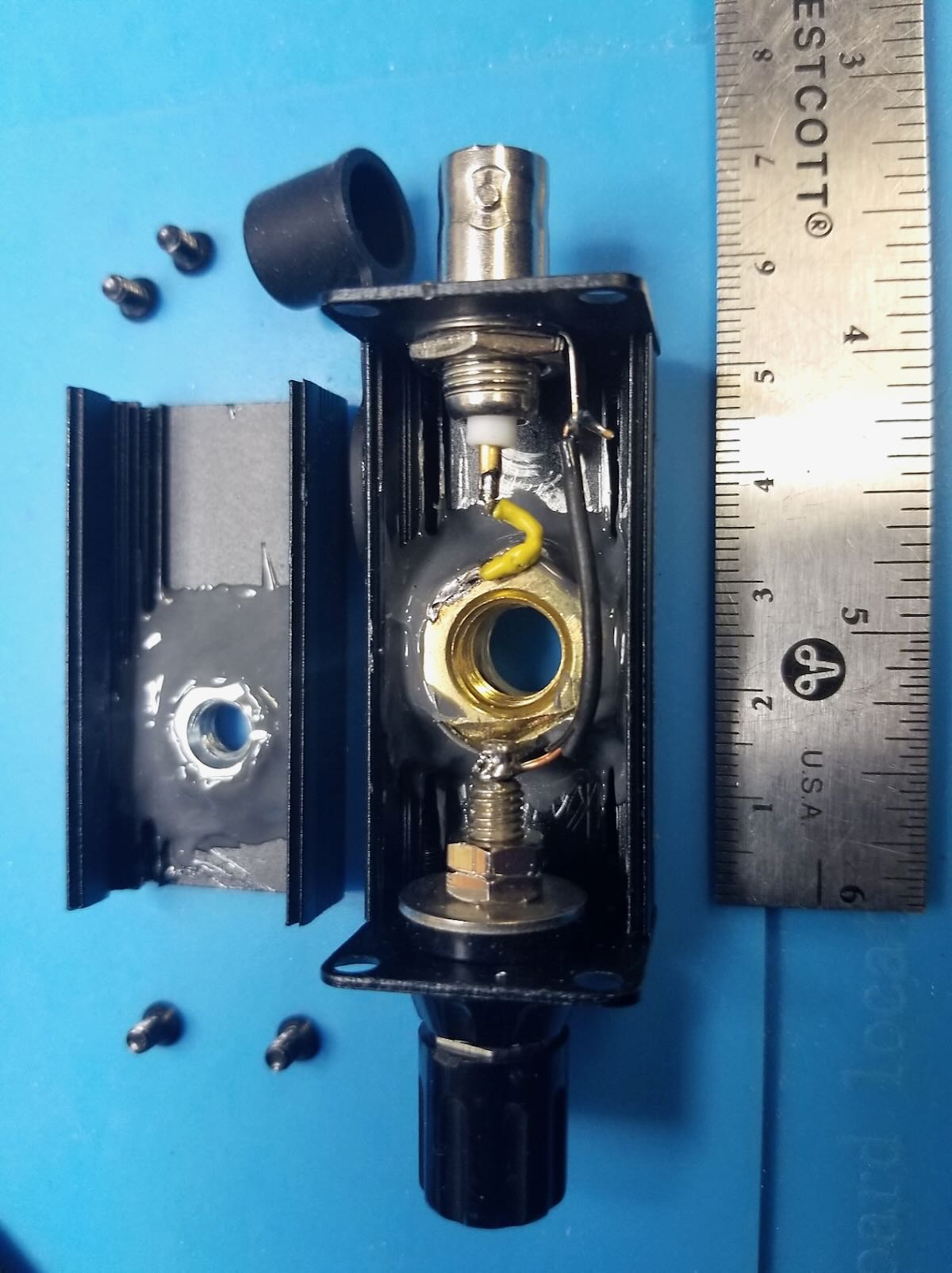
Figure 2 – Antenna mount unclamped from top of monopod. The black plastic fitting (at right, with wedge-shape) fits into slot on platform at top of monopod (at left) and clamps in with cam arm. Large steel screw attaches wedge fitting to antenna mount case. Ruler shows scale of things.
Figure 3 – Antenna mount case (right) unscrewed from camera mount fitting. Steel screw is standard camera mount size (1/4-20 thread size). Black silicone cap keeps dust out of BNC connector. If your camera mount does not have a detachable wedge fitting (like the one on the left), you would simply screw the camera mount screw directly into the bottom of the antenna mount case.
Figure 4 – Top of monopod dissembled to show (clockwise from top): black monopod tube with telescoping whip stored inside (stainless steel with 10 mm brass mounting bolt), antenna mount case, detachable camera mount fitting, and round top plate of monopod. For my monopod, I had to remove one tiny screw and apply gentle torque to break a weak glue joint of this round piece on top of the monopod leg. It remains a snug hand fit (no screw needed).
Figure 5 – Fully assembled whip antenna mount with wiring. Radial (blue wire) with tie-off cord (yellow) at left; RG174 coax (5 m) at right. Whip is only ever screwed in hand-tight. Deploying in the field, I first tie off the monopod to something (park bench, picnic table, fence, tree), then screw the collapsed whip into the antenna mount and clamp mount on top of monopod, then plug in radial and tie the yellow cord off to something (straight out at 2 m height or slope down to ground anchor), and finally connect the coax to the rig. When all in place, I carefully raise the whip (slowly, with two hands to reduce bending forces). Take-down is all in reverse.
Figure 6 – Detail of antenna mount case. Case is 50 mm x 25 mm x 25 mm aluminum clam shell box with square metal end plates. These end plates are screwed in to hold the two halves together. White plastic bushing provides additional lateral support for the whip when it is screwed in. The bushing is glued to outside of case with CA (Krazy) glue.
Figure 7 – Inside of antenna mount case. On left, a ¼-20 steel nut is epoxied to inside of case with strong JB Weld epoxy. In main case, a 10 mm brass nut is epoxied to inside of case with an insulating washer beneath. This brass nut connects to the whip and is “hot”, so must be insulated from the black aluminum case. Yellow wire connects center of BNC to brass nut (soldered). Black wire connects ground side of BNC to radial banana jack. Use plenty of epoxy; there is a lot of force exerted on the steel and brass nuts.
Figure 8 – Detail of inside of case. Note separation of banana jack solder post and edge of 10 mm brass nut. Solder yellow wire to nut before epoxying in nut.
Hope you find this useful. Just use what you have on hand and some ingenuity to make yours!
Connecting an international community through low-power field radio adventures.
Please support QRPer by adding us to your whitelist in your ad blocker. Ads are what helps us stay online. All of our ads are ham radio related--no junk, we promise! Thank you!