
by Matt (W6CSN)
Bletchley Park
 Most readers of this blog are probably familiar with Bletchley Park and the significance of this place in breaking the codes used by the axis military forces during the second world war.
The electromechanical systems developed and used here to aid the codebreakers in their daily work led directly to the electronic digital computers of the mid-twentieth century, and then to the modern world as we know it.
 After boarding the London Northwestern Railway at Euston station, the hour long train journey took us from central London, through the suburbs, then the pastoral English countryside to the station at Bletchley, just south of Milton Keynes.
 Bletchley Park is a five minute walk from the train station at Bletchley, the town of the same name. In keeping with the formerly clandestine nature of the work at Bletchley Park, there are no loud signs to welcome you, just the Union Jack flying over the nondescript visitor center in Block C.
 Exiting the visitor center, any ham will quickly spot the three-element SteppIR Yagi perched atop a roof-mounted tower. Also from the tower, a folded dipole extends over the the Block B building which houses the Alan Turing museum exhibits. The other end of this antenna farm is plugged into GB3RS, the amateur radio station for the National Radio Centre of the RSGB.
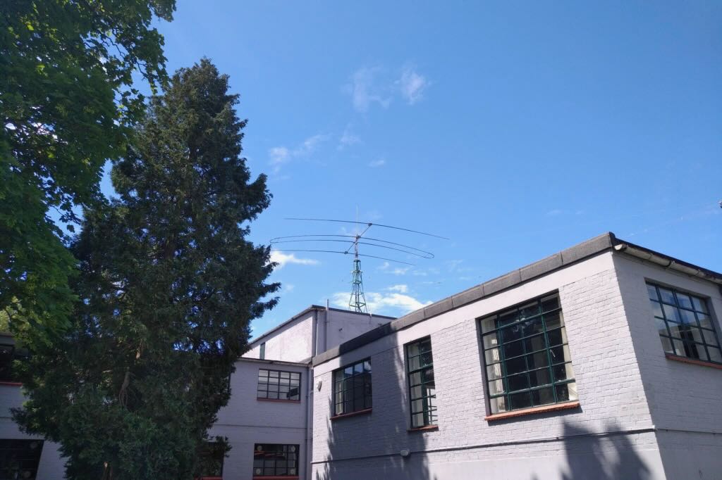 The friendly and helpful staff of amateurs at the NRC played a crucial role in my hoped-for plan of activating Bletchley Park for Parks On The Air.
Surprisingly, the POTA page for GB-0507 showed only a handful of activations of this iconic location. Seeing as this is a heritage site, I sent an email to the NRC about week before my visit asking for advice on how to be a welcome guest POTA operator.
 Note, the NRC is colocated on the grounds of the museum but they are not a part of Bletchley Park. The NRC is a separate organization.
Martyn G0GMB, the Director of the NRC, kindly responded to my enquiry and informed me that individual amateur radio activity is not generally permitted on the grounds of Bletchley Park due to the number of visitors they receive and concerns about RF safety. This could explain the low number of activations.

Martyn suggested I could set up in the overflow car park few minutes walk down the road from the visitor center. While not on the grounds of Bletchley Park proper, the parking lot operation would still be in the spirit of POTA and would reasonably count as a valid activation location.
When I arrived at Bletchley Park on Friday afternoon, I was met by Mervyn G4KLE who was expecting me thanks to a note left by OM G0GMB. Mervyn asked where all my equipment was and I motioned to the pack on my back.
Because my radio and antenna was a low impact, minimal footprint QRP setup, I was told that I could make use of the picnic table just out the side door of the GB3RS shack, with my antenna setup just beside it. This dead-end spot was not on any of the paths frequented by park visitors and my antenna would not be easily visible.

This was a much better arrangement than trying to activate from a car park without a car! I quickly deployed a GRA-GNT micro tripod with center spike pushed easily into the soft ground. The GRA-7350T loaded vertical and a set of short radials provided an SWR of 1.05 to 1.
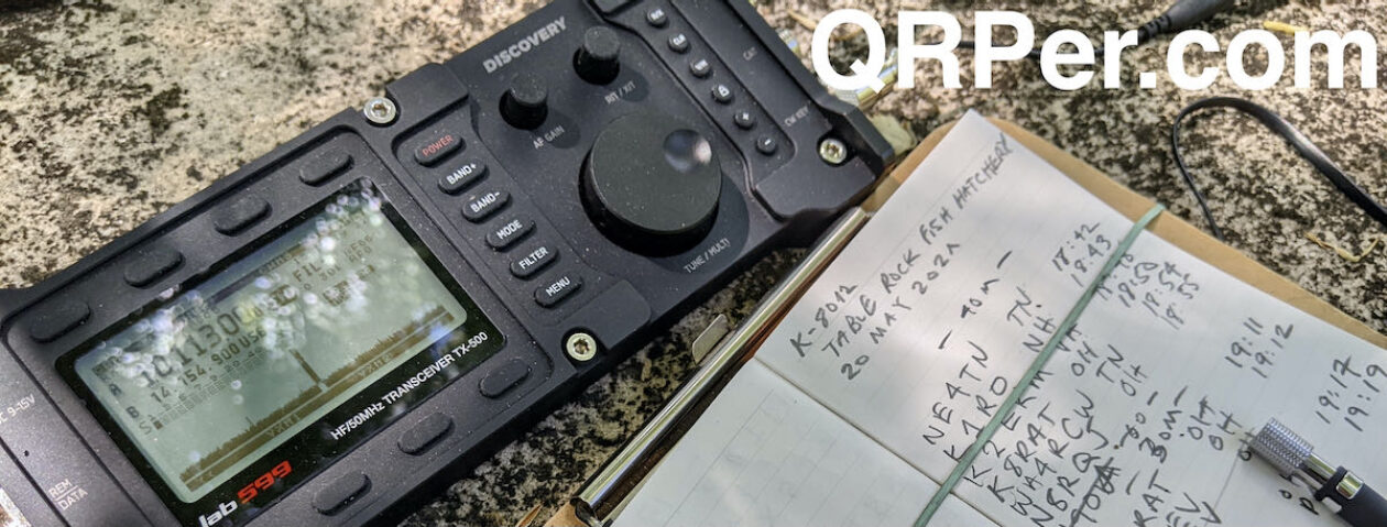
 I chose the QMX as a travel radio while in Britain because with it, the overall kit is very lightweight and compact. With the exception of the tripod the whole kit fits in my carry-on. The GRA-GNT antenna mounting kit has to fly in checked baggage due to several aggressive looking spikes that would certainly be flagged by airport security. Continue reading UK POTA Rain and Shine


