Tag Archives: Verticals

Construction Notes: VO1DR Monopod Antenna Mount

Many thanks to Scott (VO1DR) who shares the following guest post:


Construction Notes – VO1DR Antenna Mount for Camera Monopod

by Scott Schillereff,  VO1DR

Further to my article about radio during trip to Portugal, a number of readers asked for details on how I mounted my whip antenna system to my camera monopod for /P use.  Here are some photos and notes on this.

General notes:

  • This is a “straight-through” design.  Just direct connections from the BNC center pin to whip (via brass nut), and BNC housing to radial connector.
  • This is not a cook-book construction article, rather just a show-and-tell of how I built mine.  You can use what you have on hand to build something similar.
  • I suggest you start with your telescoping whip, so you know the size and threads for mounting bolt.
  • You could use any type of connector for the radial (wingnut, knurled nut, spade lug, alligator clip, whatever you like).  I prefer banana jacks since a) I can push in the radial banana plug fast, b) the plug is a weak release point (pulls apart if someone walks into the radial), and c) I can easily attach additional radial wires, if desired.
  • Use a strong case (metal clamshell or cast aluminum work well).  With the whip extended, there can be substantial forces (bending moment) from wind or handling. A tiny plastic case would be fractionally lighter but might fail.
  • For size, the one I used (25 x 25 x 50 mm; 1” x 1” x 2”) is about as small as I would go.  It needs to have a big enough footprint to sit firmly on a camera mount fitting.
  • Use high heat (e.g., Weller 100-140 W solder gun) when soldering the center pin wire to the brass whip mounting nut.  Solder the wire to the brass nut before you epoxy the nut.
  • I custom made the white plastic insulating bushing (where whip screws in). This was from a nearly-right bit from my junk box.  You can be creative here.  You could also epoxy on short piece of close-fitting, thick-walled PVC pipe around the outside of the whip mounting hole as a supporting sleeve to give some lateral support to whip when it is screwed in.
  • Dry-fit everything (before epoxying) to make sure nothing touches that shouldn’t and you can screw in the camera nut and whip fine.  Test proper continuity of center pin and radial connections to BNC fitting.  Once glued, there’s no going back!
  • For surfaces to be epoxied (metal nut sides and bottom, insides of mounting case), slightly roughen with sandpaper or jewellers file, then clean with isopropyl alcohol and Q-tip.  This will increase adhesion and strength.
  • Use good-quality, high-strength, long-cure epoxy (e.g., JB Weld), not el-cheapo 5-minute epoxy from the Dollar Store.  LET THE EPOXY COMPLETELY CURE BEFORE MESSING WITH IT!  Just walk away from it for a day… (your patience will be rewarded).

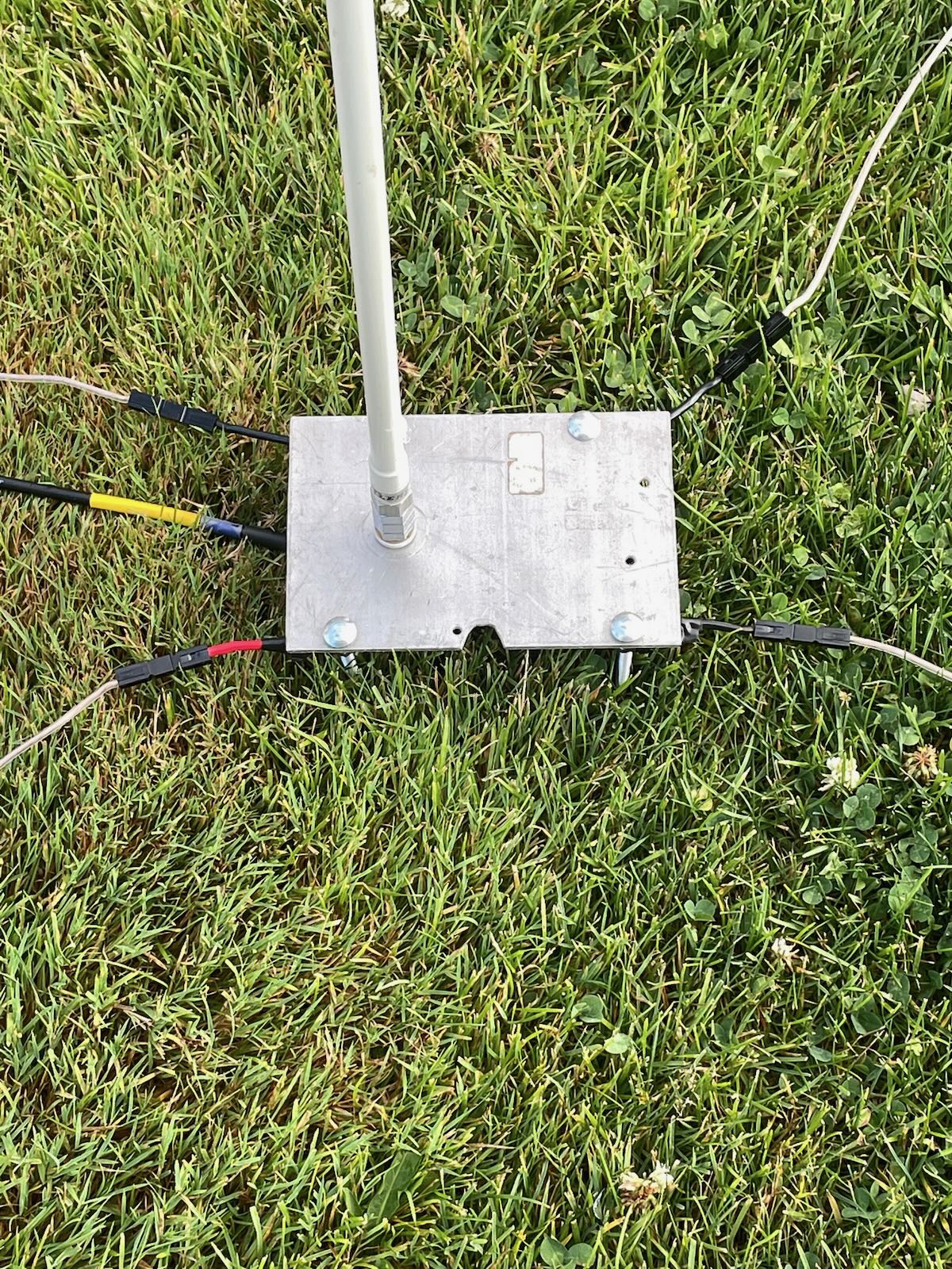
Figure 1 – VO1DR Antenna Mount, clamped onto top of monopod.  Coax goes to BNC on left; whip screws into top; raised radial connects by banana plug on right

Figure 2 – Antenna mount unclamped from top of monopod.  The black plastic fitting (at right, with wedge-shape) fits into slot on platform at top of monopod (at left) and clamps in with cam arm.  Large steel screw attaches wedge fitting to antenna mount case. Ruler shows scale of things.

Figure 3 – Antenna mount case (right) unscrewed from camera mount fitting.  Steel screw is standard camera mount size (1/4-20 thread size).  Black silicone cap keeps dust out of BNC connector.  If your camera mount does not have a detachable wedge fitting (like the one on the left), you would simply screw the camera mount screw directly into the bottom of the antenna mount case.

Figure 4 – Top of monopod dissembled to show (clockwise from top): black monopod tube with telescoping whip stored inside (stainless steel with 10 mm brass mounting bolt), antenna mount case, detachable camera mount fitting, and round top plate of monopod.  For my monopod, I had to remove one tiny screw and apply gentle torque to break a weak glue joint of this round piece on top of the monopod leg.  It remains a snug hand fit (no screw needed).

Figure 5 – Fully assembled whip antenna mount with wiring.  Radial (blue wire) with tie-off cord (yellow) at left; RG174 coax (5 m) at right.  Whip is only ever screwed in hand-tight.  Deploying in the field, I first tie off the monopod to something (park bench, picnic table, fence, tree), then screw the collapsed whip into the antenna mount and clamp mount on top of monopod, then plug in radial and tie the yellow cord off to something (straight out at 2 m height or slope down to ground anchor), and finally connect the coax to the rig.  When all in place, I carefully raise the whip (slowly, with two hands to reduce bending forces).  Take-down is all in reverse.

Figure 6 – Detail of antenna mount case.  Case is 50 mm x 25 mm x 25 mm aluminum clam shell box with square metal end plates.  These end plates are screwed in to hold the two halves together.  White plastic bushing provides additional lateral support for the whip when it is screwed in.  The bushing is glued to outside of case with CA (Krazy) glue.

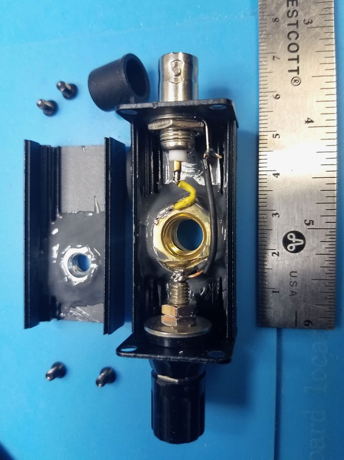
Figure 7 – Inside of antenna mount case.  On left, a ¼-20 steel nut is epoxied to inside of case with strong JB Weld epoxy.  In main case, a 10 mm brass nut is epoxied to inside of case with an insulating washer beneath.  This brass nut connects to the whip and is “hot”, so must be insulated from the black aluminum case.  Yellow wire connects center of BNC to brass nut (soldered).  Black wire connects ground side of BNC to radial banana jack.  Use plenty of epoxy; there is a lot of force exerted on the steel and brass nuts.

Figure 8 – Detail of inside of case.  Note separation of banana jack solder post and edge of 10 mm brass nut.  Solder yellow wire to nut before epoxying in nut.

Hope you find this useful.  Just use what you have on hand and some ingenuity to make yours!

Best 72, Scott  VO1DR

Barry reviews the PAC-12 portable antenna

Many thanks to Barry (KU3X) for sharing the following guest post originally posted on his website:


Product Review: PAC-12 Portable Multi Band Vertical Antenna

by Barry G. Kery, KU3X


I am always on the hunt for a better mouse trap. Dave, NB3R came across a great multi band vertical antenna for portable operating. It’s a, “ PAC-12 7-50MHz Shortwave Antenna “ found on AliExpress.com.

The PAC-12 antenna is designed to operate on any frequency from 6 meters down to 40 meters.

Numerous manufactures make multi band vertical antennas designed to be used for portable operating. Some have quality issues and others may have performance issues, or both? Any hunk of wire or aluminum will radiate if RF is applied to it, but how much will be radiated is the question.

When it comes to ground mounted vertical antennas, one major factor that effects performance is the ground radial field. The PAC-12 comes with a long ribbon cable that you will have to separate each wire and cut to a quarter wave length per band of operation. There are ten wires within the ribbon cable. The length of the ribbon cable is 18 feet. This is too short for 40 meters but perfect for 20 meters. I made four 35 foot long radials out of some wire I had laying around the shack. This will increase the performance on the 40 meter band as well as making a better match. Spread the radial wires out equally around the base of the antenna.  Since the radials are not elevated, they do not have to be tuned but it does make for a better match.

The antenna comes with a short stake that can be driven into the ground for attaching the ground radial crimp on to and attaching the feed insulator.

The stake is strong enough to support the entire antenna, even on windy days. The feed insulator has an SO-239 for connecting your coax. The feed insulator must be attached to the ground stake correctly. Make sure the writing on the insulator is on top of the SO-239 and the black portion of the insulator is attached to the ground stake.

So what makes this antenna perform better than most other commercially made portable vertical antennas? Answer, “the mast!”

Most manufactures, not all, use a tapped base loading coil to make the antenna resonant on numerous bands.  On a quarter wave antenna, the wire or aluminum closest to the feed point of the antenna is the current portion of the antenna and the current portion does the most radiating. Continue reading Barry reviews the PAC-12 portable antenna

Choosing between the Chameloeon MPAS Lite and Chelegance MC-750 vertical antennas

The Chameleon MPAS Lite

Over the past few months I’ve been asked by a number of readers and subscribers about the differences between the Chameleon MPAS Lite and the Chelegance MC-750.

More specifically, folks who are looking for this type of portable HF antenna want to know which one they should buy. I have difficulty answering questions like this in an email or comment because I need to understand the operator first.

At the end of the day, both of these antennas are excellent choices; the decision has more to do with your own personal preferences and how you see yourself using the antenna.

Why buy a vertical?

The Chelegance MC-750

I believe every serious field operator ought to have at least one vertical antenna option available. Depending on where you’re operating, verticals might not be the highest-performing antenna you could deploy, but they may be the most convenient and rapid to deploy. Then again, if you’re sitting on the beach at the ocean or sea, a vertical can be a phenomenal DX antenna.

Verticals aren’t terribly difficult to build. In fact, one of the first field antennas I built many years ago was a 20 meter vertical, albeit with wires instead of telescoping whips.  That said, it’s difficult for some of us to build something as high quality and as durable as a commercially-produced vertical antenna system.

Both the MC-750 and MPAS Lite antennas are high-quality and very quick to deploy. I reach for them frequently because I often have only a short time on the air and any time saved setting up the antenna usually leads to more SOTA and POTA contacts.

MC-750 / MPAS Lite Comparison

Instead of writing a full article about the differences, I made a video where I discuss these two antennas at length. My focus and goal being to help those who are trying to make a purchase decision.

At the end of the day, I don’t think you could go wrong with either antenna system, but I do do think one may suit you slightly better based on your operating style and goals.

Enjoy:

Video

Click here to view on YouTube.

Below, I’ve also listed some key features and specs of both antennas along with links that you might find helpful:

Chelegance MC-750

  • Price: $179 + $50 shipping (via Chelegance)
  • Whip length: 5.2 Meters/17.06 Feet
  • Counterpoise: Quantity of four 11.48 foot counterpoises
  • Frequency range: 40M – 6M
  • Resonance markings: Yes (save 30M and 6M on current version)
  • Carry case: Yes, padded case included with purchases
  • Product manual (PDF)
  • Product Link

Chameleon MPAS Lite

  • Price: $360.00 (via Chameleon)
  • Whip length: 5.18 Meters/17 Feet
  • Counterpoise: 60 feet of tinned copper KEVLAR PTFE
  • Frequency range: 160M – 6M
  • Resonance markings: No
  • Carry case: No (Optional large backpack from Chameloen)
  • Includes 50 feet of high-quality coax with inline RF choke
  • Product manual (PDF)
  • Product Link

POTA/SOTA Activation Video Playlists:

Dale uses WSPR to test counterpoise orientation

The CHA MPAS Lite

Many thanks to Dale (N3HXZ) who shares the following guest post:


Does your antenna counterpoise orientation matter?

by Dale (N3HXZ)

I am an avid SOTA and POTA activator and love field operation. I use a portable vertical whip antenna with a single counterpoise for my antenna system and have always wondered if orienting my counterpoise would provide some signal strength gain in a particular direction.  I decided to run a series of tests using WSPR to gather field data, and use statistics to answer the question:

Does one counterpoise orientation favor another in terms of average signal strength?

WSPR is a great tool for antenna testing. You can study various antenna configurations by making some WSPR transmissions and then checking the data on the WSPRnet database to see how well the signal was received at various stations located all over the world. You have to be careful in interpreting WSPR data though as receiving stations have different antenna and radio configurations, and the band propagation can vary rapidly at times. So how do you take advantage of all the data you receive from stations and draw some meaningful conclusions? I have found that using proven statistical theory in analyzing the transmitted signal strength received from individual stations can provide you results that you can confidently trust.

So what statistical algorithm is helpful?

For antenna signal strength comparison between two configurations, you can use an independent two-sample t-test with a one-tailed t-test evaluation. It sounds like a mouth-full, but it is quite simple. For our purposes, the t-test compares the average signal strength at a given receiving station from two different antenna configurations. The one-tailed test validates or invalidates the hypothesis that one antenna configuration produces an average signal strength greater or less than the other antenna configuration.

The testing requires that you run WSPR long enough to gather multiple reports at a single receiving station for both antenna configurations. Using the signal strength reports, you compute the average signal strength and the standard deviation of the signal strength over the sampled data points. Excel can easily provide that data.  With this information and the number of sample points for each antenna configuration (they can be different), you then run a calculation by hand or in Excel to compute the ‘t’ value.

This ‘t’ value is then compared to a critical value for the number of sampling points from a ‘Students t table”. If the ‘t’ value is less than the critical value you can confidently conclude that the hypothesis is false and therefore conclude that there is no significant difference in the mean value of the signal strengths between the two.  If the ‘t’ value is greater than the critical value you can accept the hypotheses that one antenna configuration produces a greater or less average signal strength than the other configuration. Continue reading Dale uses WSPR to test counterpoise orientation

Guest Post: Reviewing the Chelegance MC-750 (Part 1)

Many thanks to Charles (KW6G) who shares the following guest post:


Product Review: Chelegance MC-750 Portable Ground Plane Antenna, Part 1

by Charles Ahlgren, KW6G

I recently purchased a Chelegance MC-750 portable ground plane antenna from DX Engineering.  Essentially, the antenna system provides a ¼ wave portable vertical antenna with 4 counterpoise wires that operates on 20 through 10 meters.  The antenna will also operate on 40 meters with the provided loading coil.  The manual states the antenna will support 6 meter operation, but no instructions are provided on how to do so.  30 meter operation is not supported.   It appears from our initial testing that no ATU is required.

Here are some of my thoughts on the antenna.

Product Description

The MC-750 comes with the following components:

  • GROUND ROD / ANT BASE
  • 50 CM ANT ARM
  • 5.2 M WHIP
  • 7 MHZ COIL
  • 4  COUNTERPOISE WIRES (radials)
  • COUNTERPOISE WIRE COLLECTOR BOARD
  • CARRY BAG

As provided, it is designed to operate on  the 40, 20, 17, 15, 12, and 10 meter bands without any modifications.  Six meters is also supported per the manufacturers manual, but no guidance on how to do that is offered in that document.   However, finding the proper length of radiator for 6 meters should be straightforward using a tape measure to set the proper whip length.

[Update: Chelegance notes that to operate 6 meters, simply extend the last segment only of the whip (see photo) and for 30 meters extend the last four segments of the whip and 15cm on the 5th segment (see photo).]

I checked the ground rod / antenna base with a magnet and confirmed it is made from stainless steel as both components are not magnetic; a characteristic of stainless.   Both the ground rod/ antenna base and the 50 cm antenna arm (which was also non-magnetic) had a hefty feel (together, they weigh about 2 pounds), therefore I think it safe to assume that these components are made of stainless steel.  Since most ops will undoubtedly use the antenna arm as an aid to inserting / extracting the ground rod into / from the ground, it seems a prudent decision by the manufacturer to have this piece fabricated from a strong, stiff  material such as steel.  The machine work used to fabricate these parts appears to be quite good – the fit and feel were excellent, with no sharp or ragged edges to cause problems in the field.

I measured the whip while set at the various position marks for 20 through 10 meters.  The band markings on the whip were accurate – giving a 1/4 wavelength radiator when combined with the 50 CM ant arm length…On 40 meters, the whip and rod measured about 1/8 wavelength.  The required the loading coil needs to be inserted between the whip and the rod (at approximately 1/10 the total 40 meter whip height above the base).  If you want to operate this antenna on 30 meters, it appears that you need to provide an extra 1.4  meter of additional rod as a quarter wavelength ground plane at 10.1 MHz  requires a 7.1  meter radiator.  Six meter operation would require a whip of around 4.7 feet.  With the whip fully collapsed, the length of the rod and antenna arm measures 40-1/4”.  Therefore, if 6 meter operation is contemplated, extending the whip about 16 inches from fully collapsed should suffice.  However, I don’t think that an antenna configuration such as that would be a very good performer unless it were elevated from ground level; or maybe it would be good for a SOTA activation? Continue reading Guest Post: Reviewing the Chelegance MC-750 (Part 1)

Steve’s Homebrew Vertical Antenna for POTA

Many thanks to Steve (KM4FLF/VA3FLF) for sharing the following guest post:


A Great Homebrew Vertical Antenna

by Steve (KM4FLF/VA3FLF)

Last spring, I was going through my many boxes of ham “stuff” looking for items to sell at our club tail gate sale. I came across a couple of Hustler SM Series Resonators (20 /40 Meters) that I had acquired. I am not sure where I obtained them, but I decided they were keepers.  That decision turned out to be the first step in a year long process that has given me an awesome homebrew vertical antenna.

After doing a little research I found the resonators and accessories at most of the online ham dealers. They are used primarily as mobile and marine antennas. I had seen where a ham had used these on a ground stake as a portable antenna as well. I ordered a Hustler MO1 mast which is 54 inches tall and thought I would attempt to make a portable POTA antenna.

Antenna base

I had a couple of small aluminum plates that I drilled out a few holes. I cut out a notch to put a SO-239 Stud Mount on the plate as my antenna base. I now had a ground plate, connector, and antenna with resonator. By putting a stake in the bottom of the plate, I was able to get the antenna to stand up. The Hustler resonators have a hex screw for tuning that can be loosened. The antenna can be adjusted for resonance by lengthening or shortening the radiator length. After adjusting the radiator my SWR was still horrible on the two bands.

Antenna base close-up

I had some 14-gauge wire laying around and attached it to the plate using carriage bolts and nuts for my ground radials. I didn’t think about the length of the wires at this point but went with three or four lines around 20 to 30 ft. I was able to use my vertical a few times with moderate success. My SWR on 20 and 40 Meters was around 2:0 to 1 at best. It was bulky and very delicate. Sometimes screwing in or unscrewing the MO1 the SO239 would slide off the edge of the aluminum plate. I put away my contraption for the winter and decided to move on to something else.

In April of this year, I wanted to revisit my project. Continue reading Steve’s Homebrew Vertical Antenna for POTA