(Note: I cut my Florida POTA trip short as I needed to take care of some personal business. I apologize for the change of plans and the inability to communicate that to y’all. I appreciate everyone’s support of the trip and the QSOs of those who hunted me. Articles will be forthcoming for those activations in the near future.)
Those of you who have followed my journey on QRPer know that I wrote an article about my kit for the trip I took last summer to Nova Scotia. Since then, what ham radio equipment I take with me has changed, partially because I am not flying to a different country far from home and partially because of my experiences with what I generally do and don’t need. I thought I’d share what my kit currently looks like for the spring-break Florida trip.
Here is a photo of what ham radio-related gear I am taking on my Florida POTA trip. We’ll first look at what I have in each section of the Elecraft bag I take with me and then a few items that do not fit in this bag but are still along for the ride.

When I purchased my KX2, I also purchased the Elecraft bag. Though the bag is bulky in its profile, it was a worthy purchase due to the amount of stuff it can store in one place in a well-organized manner.

The bag has three compartments.

In the first compartment is my main man, Craig, my KX2. He is the rig I use for all my QRP adventures out and about. I do have a protective cover I purchased for him but haven’t installed yet. I have a fear of messing with electronics and, though installing the shield isn’t rocket science, the project seems overwhelming enough that I haven’t tackled it yet.


Also in this first compartment are my throw bag containing an arbor line and throw weight, some S-carabiners, my homemade radials for the AX1, the tripod mount for the AX1, and a pencil and earbuds. I find I copy CW much better when I have a headset of some sort.
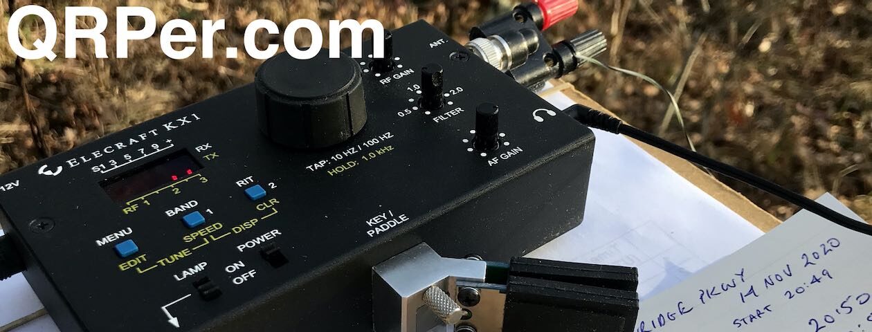
In this compartment, I used to have a back-up key. However, in its place is a new single-lever paddle from CW Morse [QRPer affiliate link]. I am using this key because it is wired to be a cootie or a paddle via an internal switch. I discovered my KX2 doesn’t balk at using this key like a cootie unlike when I use the CW Morse SP4. I desire to use QRP for more than POTA, specifically for SKCC and calling CQ for ragchews. SKCC requires a mechanical key and, as the cootie is my favorite key, this new key should fill the need I discovered the last time I visited Skidaway Island.
In the second compartment, I have the AX1 and the Tufteln EFRW antenna. Those of you who have read my articles know I generally deploy the Tufteln EFRW antenna. On this April Florida trip, I plan to use the AX1 and the Chelegance MC-750 more often in preparation for my summer POTA trip. I anticipate I’ll be limited by terrain and park rules from deploying an antenna in a tree so more experience with verticals will be helpful.


In the third and final compartment are some odds and ends: neon pink flagging tape, an allen wrench for adjusting my CW morse keys, some twine, a short length of wire with an alligator clip on the end, two shock bungee cords, the cord for my CW Morse single-lever key, and a splitter for the headphone jack. I’ve used all these items (except the cord for the new key) at one time or another so I don’t want to leave the house without them.


Here are items I am also taking that don’t fit in the Elecraft bag.
The Tufteln kneeboard, POTA flag, and a notebook. I really like using pencil and paper for my POTA logs. I hold my key in the left hand and send with the right. For some reason, juggling that with paper is more manageable to me than logging in my phone or a laptop. The one thing I miss out on by doing that, though, is not knowing people’s names except those I’ve encountered many times. (And even then I forget names in the busyness of an activation so if I do, please forgive me.) I like to thank people by name at the end of the QSO rather than just their call sign if I know their name. I learned to do this in SKCC exchanges and I think it is a respectful and genteel practice. The one advantage I see to using a logging program is that I could do that with every QSO.


In a Tom Bihn bag, I have my RG-316 coax in three lengths (10’, 20’, and 50’), a short bungee cord, a stereo connector, and a newer version of the SP4 (aka The Minion).


Also coming along for the ride is the Chelegance MC-750. [QRPer affiliate link]

The last pieces of equipment I am bringing are for the first park I will visit – Lafayette Wildlife Management Area. In areas that allow hunting, Daisy and I wear blaze orange, even in the off season. Though as hams we try to be law abiding, we need to remember there are others out there who are not. When it comes to areas in which hunting is allowed, it is wise to wear blaze orange year-round because hunting violations due happen.

There you have it – the POTA Babe’s current QRP kit. I have one last question to address in this series – how I plan my trips. To find out, stay tuned…