NOTE: I am embarrassed to admit that I made a significant error in my original measurement methodology and the numbers originally listed below were inaccurate. I’ve redone all the measurements and the text and tables below reflect the corrected measurements. *
Your host, K4SWL, asked me to share my experiences in trying to find a small, lightweight, battery pack for use with my field-portable QRP station. While I’m looking for a battery pack specifically for my Elecraft KX1, what I’m learning should be useful for users of any low-current QRP transceiver.
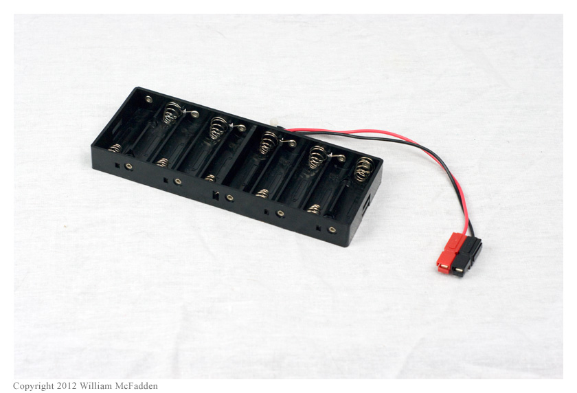
Currently, I’m experimenting with a pair of ten-cell AA battery-holders, one of unknown provenance (photo) and a new, more rugged one from Batteries America (p/n 10AAT, photo). When filled with ten AA NiMH cells, the resulting battery-packs provide about 14v at full-charge. At the 2012 Flight of the Bumblebees, my KX1 generated an indicated 2.6w on 20m and 4w on 40m while being powered by one of these packs; the nearly four hours of low-stress operating during this event did not discharge this pack of 2,000mAh cells very deeply. The use of two AA dummy-cells will also allow the use of eight lithium primary or alkaline cells in an emergency.
I became concerned about using this style of spring-contact battery-holder when I found an article (link) by Phil Salas, AD5X, in which he reported that this sort of battery-holder is likely to display significant voltage drop under load.
I tested my original battery-holder with ten 2,000mAh NiMH cells and my KX1 transmitting into a dummy load. In addition to measuring whole-pack voltage-drop, I measured the voltage-drop of each of the individual 2,000mAh cells as I transmitted into the dummy load on 20m.
Original Battery-Holder / 2,000mAh cells
Band
ΔVpack
ΣΔVindiv.
20m
0.76v
0.52v
30m
0.79v
—
40m
0.75v
—
80m
0.70v
—
The sum of these individual drops was 0.52v, so I’m losing 0.24v in the spring-contacts and/or battery-holder’s “transistor battery” output connector.
After replacing the original nylon connector with a pair of Anderson Powerpoles, I tested the same 2,000mAh NiMH cells in the new, more rugged battery-holder, this time only on 20m:
New Battery-Holder / 2,000mAh cells
Band
ΔVpack
ΣΔVindiv.
20m
0.73v
0.53v
I’m losing about 0.20v in the battery-holder’s spring-terminals, slightly less than with the older battery-holder.
The 0.20v ~ 0.24v drop from the spring-terminals doesn’t seem excessive to me and the difference in these measurements between the two battery-holders is probably not significant. I am more concerned by the 0.53v ~ 0.54v voltage-drop I measured in the individual cells. It is likely that these older 2,000mAh cells, which have been cycled many times, are exhibiting greater voltage-drop than new cells would. To test this theory, I purchased new 2,100mAh cells to measure.
I measured the new cells as above, again on 20m into a dummy load, and found that with each of the battery-holders, the sum of the individual cell voltage-drops was 0.22v, so my speculation appears to have been correct–the new cells do have lower voltage drop under load than the old cells do.
Orignal Battery-Holder, 2,100mAh cells
Band
ΔVpack
ΣΔVindiv.
20m
0.48v
0.22v
New Battery-Holder, 2,100mAh cells
Band
ΔVpack
ΣΔVindiv.
20m
0.47v
0.22v
The new 2,100mAh NiMH cells are marketed by Polaroid and cost $6 per four-pack at Big Lots; the least expensive AA NiMH cells available at Batteries America, 2,500mAh Sanyo cells, cost $3 each at the time of this experiment. I don’t know if the Polaroid cells will last for as many cycles as the probably-higher-quality Sanyo cells would but trying the significantly less expensive Polaroid cells seemed like a a good gamble.
As indicated above, the new battery-holder (Battery American p/n 10AAT) is more rugged than my original battery-holder; it holds the AA cells more securely and and doesn’t use a “transistor battery” connector to connect to the load. I replaced the original nylon connector with a pair of Anderson Powerpoles. This battery-holder will be my preferred battery-holder for field operations with the KX1.
In his article (link), Phil Salas, AD5X, recommends foregoing battery-holders in favor of soldered/welded battery packs but I will continue to experiment with battery-holders. I prefer to charge my NiMH cells individually, using an intelligent MAHA charger, rather than charging an entire pack. In addition, my KX1 draws significantly less current on transmit than Phil’s IC-703 does so the the IxR losses I’ll experience will be less significant than that which Phil experienced.
* What had I done wrong? I discovered when testing my new battery-holder that the previous measurements of the old and new NiMH cells in the original battery-holder had been made with the KX1 transmitting into a 50Ω dummy load with the KX1 autotuner configured in tune mode instead of in bypass mode; because the KXAT1 autotuner doesn’t sense a mismatch and automatically tune, this meant that transmitter current–and the measured IxR voltage losses–might be also be significantly different than with the KX1 transmitting into a matched load. Comparisons of my original numbers to measurements made later of the new battery-holder wouldn’t be meaningful, so I had to do all the measurements again.
This year, during our family’s summer holiday, I’m enjoying the hospitality of Prince Edward Island, Canada (hence, the lack of recent posts on QRPer). This is our family’s second visit to the maritime island, and each time we’ve been fortunate to stay at the same off-the-grid cabin on the eastern coast, less than twenty meters from the water.
Of course, staying in an off-grid cabin comes with its radio challenges—namely, supplying power—but also comes with one supreme advantage: no noise from the typical electrical devices that plague most of our homes. What’s more, this cabin sits on 60 acres, so not even a neighbor’s home appliances disturb my RX ears.
On our previous visit, I brought my (then) Yaesu FT-817, a 9aH gel cell, Micro M+ charge controller, 10W Solarex PV panel, some 300 ohm window line, loads of 22 AWG wire and an LDG ATU. Unfortunately, I found I had very little time for radio, and propagation was dismal. Indeed, it was during that trip that I discovered my FT-817’s finals had blown, so part of the time I was transmitting less than QRPpppp levels.
This year, since I knew the site well, I came better prepared.
My full 2012 setup consists of the following:
An Elecraft K2/10
An Elecraft KX1 (4 band w/built-in ATU)
Elecraft T1 ATU
LDG 4:1 Balun
One 35 aH gel cell
Two 9.5 aH gel cells
Two PowerFilm Solar foldable 5 W PV panels
My radio toolbox with various connectors, crimpers, cutters, wires, caps, multi-tester, etc.
Enough wire and 300 ohm antenna line to make a couple of wire antennas
So…how’s it all working out? Brilliantly!
In the past few years I’ve done a lot of QRP CW—mainly rag-chews with some buddies on the lower bands. I’ve done less QRP SSB phone. When I first arrived at the cabin and began the process of unpacking, I couldn’t find the jumper cable to attach to my Vibroplex single-lever paddle (the paddle being a Dayton 2012 find, by the way). So, I plugged in a microphone and tuned to the phone portion of the 17 meter band.
Talk about radio fun!
I’ve once again re-discovered the joy of operating QRP SSB. It’s challenging to make those DX contacts and to transmit a long call sign (“VY2 portable K4SWL”) across the ether, but occasionally the propagation gods smile upon you, and you’re able to participate in a good rag-chew or quick DX with a 57 to 59 signal report.
Being 20 meters from the salt water is a bonus I don’t usually enjoy in my US hermitage. Due to its excellent propagation characteristics, despite my lower power set-up, I have easily worked stations from Russia to North Africa, from the Caribbean to Japan. I am thoroughly reveling in it, and the process has re-connected me with my ham radio roots.
As Gunter, VA3GA, told me in a recent Canadian rag-chew, “ham radio holidays give you a chance to explore areas of the hobby you don’t normally think to enjoy.”
So true, Gunter. That’s what I love about ham radio in general– the hobby is so broad, you constantly discover and re-discover favorite elements about it.
The Elecraft booth has been teeming with people. Of course, large crowds around the KX3–perhaps almost as many as last year, when they first introduced this hand held QRP magic. I know I want one.
The 2 kW "Power Shade" is the right size to cover a full-size military tent.
Power Film Inc. is a developer and manufacturer of thin, flexible solar modules. The company designs, manufactures and retails their products in Ames, Iowa–a quality made-in-USA product.
Last year, at the Dayton Hamvention, PFI’s booth was very popular. Why? Their sale of small, rollable and foldable solar panels, absolutely perfect for field use, drew crowds of hams, DXers, campers, and/or frequent travelers. Needless to say, sales were brisk.
While browsing their website recently (just for fun), I came across their PowerShade™ Solar Field Shelters. They’re available in 1 kilowatt and 2 kilowatt versions at 15.4 V or 30.8 V. Wow…
This paneled tent is primarily focused at the military market. Perhaps exclusively. And I readily admit, it would be overkill for QRPers, even for a multi-op QRP Field Day. After all, aren’t we about “less is more”–?
But is it wrong for me to fantasize about this wonderful 2 kW creation? A tent-topper that sucks in Sol’s readily-available energy and, with the assistance of a battery bank, produces enough juice to fuel several QRP rigs?
Prototype of the Ten-Tec Model 539 QRP transceiver
I just received this update from John Henry (Ten-Tec Software Engineer) this morning:
Hi Tom,
We are making progress in several areas on the 539, it is coming along, and improving every day. We don’t have a price point we can speak about yet, as we are still trying to find the best working parts for a few of the items on the rig. And those parts, may affect our target. But still, we will surely beat the <$1k price that we have mentioned already. The speaker is now enclosed within the unit, similar to the 599. This is something that we knew we would eventually get done, just didn’t have it ready in time for the ham ventions to date. We will have a fully functional 539 on display at Dayton. Pre-orders at Dayton? I don’t think I will be confident enough on a real ship date yet to be able to take orders at Dayton. I don’t want to take orders at Dayton, promise a ship date, and then have it delayed for parts reasons. So, as soon as we know the parts are final, and FCC has passed, and we have all of the lead times and production times worked out and in the schedule, then we will be able to take orders. We do have the 539s in beta testing now, tweaking software here/there, finishing a few features, and soon will be able to send it to others for their inputs.
The Ten-Tec Model 418 100 Watt Amplifier on display at the 2011 Ten-Tec Hamfest. Click to enlarge.
The Model 418 100w amp is in the hands of external beta testers, and we are scheduling production start for end of May, beginning of July. The software is basically done, but of course, we are still tweaking it by adding a bit more protection and user features. We will have those added / tested / approved in the coming week or two. Beta tester input is extremely positive and they are sure we have a big hit on our hands because of everything that this amp provides is phenomenal.
John plans to give me another update just prior to the Dayton Hamvention.
My good friend, Vladimir (Vlado) Karamitrov (N3CZ/ZS6MG) is someone who likes to challenge himself. Perhaps this is why he’s such an accomplished DXer and contester.
Recently, at his QTH, he showed me one of his latest projects: a home brewed QRP transceiver. Vlado wasn’t content to simply build his own high-performance transceiver; no, he needed a built-in challenge.
Here is the story of his QRP radio, that he built mostly from junk parts, in his own words:
N3CZ's QRP rig front face
Challenge for all of us ….”Built your own radio”
By N3CZ / ZS6MG, Vladimir Karamitrov, 114 Russet Ln. Asheville, NC 28803 USA
Building your own radio is a challenge on its own. Using it to work DXCC is another challenge, probably less difficult. But combining the two brings a new spark and joy in our hobby. Isn’t ham radio about radios?
The purpose of this article is not to argue the need for building but to give ideas to those who have the time, like a new challenge and open up for ideas of building their own radios.
There are many different aspects to look into this. One is to build a radio from a kit. A search online will provide a list of manufacturers who offer these kits from basic thru intermediate to advanced designs.
The other approach is to build it your self. Yes, from scratch. Well, why not? Remember, time is what is needed most and of course some money and/or spare parts or junk parts. Time is not what I have available a lot, money is always on the agenda but having spare parts and stuff lying around your garage is another good resource.
N3CZ's workbench
So I decided to put something together. No time –means I can’t spend a lot on making this new rig look like a factory made, I have to use dead-bug design techniques and other easy methods to “glue” everything together. Available time is only after work and weekends and that is not much.
What kind a circuit and design to use? This was really the main question, because the answer will dictate what approach to take. First rule is check what parts and components you have available. There is something you have to remember here — when you go to a hamfest always bring some “junk” back home. You never know what you going to need. We all know this rule don’t we? Also don’t forget what your buddies have collected over the years, they will be able to help you with some of the missing parts if you need.
One of my passions is building my own equipment. Starting from antennas, to control boxes to switch them, pre-amps for the low bands and from time to time build a small QRP rig. Other interests are DX and Contesting, so while putting this radio together I cannot wait to hook it up to my antenna. This is where a little patience is required and I had almost none, hi. But I knew, bands are down for now, I have worked almost everything that was there to work, so will do this one little different and try to slow down a bit.
With my projects everything starts with the box. Few boxes I changed until the right one was in my hand. Next was to find a properly sized knob for the VFO. I then realized that it will take little more time to build all the components so I decided to use my $$ budget and get my self a nice DDS VFO. There are few different ones available online and for around $80. I got a nice programmable one with dual VFO’s and memories, with settable IF offset etc. This seemed to be the perfect fit for the project.
Transmitter
I thought I had all I need to start working on this project, but…..I wasn’t really sure about it yet. While looking for the “start” button and to actually take off with this project, I had yet to find that “trigger” that ignites the spark inside me, so I can say to myself, “yes I am ready, let’s just do this.”
You know the feeling – you feel a bit lazy at the beginning until that moment when that spark gets you. It’s like when you have to mow the lawn, and then you think, “no, it can wait another week, don’t feel like doing it now.” Well, I found my spark – it was not in the box, it was in the tuning knob that I got from a colleague also a ham and one who builds little QRP’s. I was actually explaining to him what I was planning to do, but not sure yet of the concept and how to handle certain parts of the circuit. While discussing all of this, he said he had some parts that he would bring for me and see if I could use some. He did not mention about any knobs, but when I saw them I knew I had what I was missing and now it iss the time to start working on this.
Transmitter PA
Now that I have the heart and the body, and the knob, I did some study of a number of different circuits published in ham radio literature including ARRL’s handbook and many online QRP resources. The goal was to build a simple radio easily reproducible, with reasonably good specifications so you can use it daily. Selection of IF frequency was the next and I decided on using 4MHz as I had access to a pile of some computer xtals of 4.032MHz.
Transmitter keying circuit and low pass filter
Junk stock provided the following:
Double balanced mixer SBL-1,
some 2N5109’s, J310 FET’s,
a few IF amps MC1350,
some toroids and
wire
I was ready to take on my own challenge – build it and work 100 countries with it!
Associated pictures with this article represent certain stages of the building process. As you can see I picked up an easy method for putting all together. I liked this approach for a simple reason that I can go step by step, keep adding components and test each stage as I move forward. There was no need for making PCB…who needs a PCB. In the old days, radios were built on a chassis and components hanging in the air and radio worked.
RX/TX antenna relay
On the other hand there was that perfection starring at me and making me feel a bit guilty, but I had no time to waste but hurry and build this radio in the short time I had available to me. Because you know what, the bands will just open up again, and then I had to do my other part – the DXing, hi so I may not be able to get this done.
I actually put the receiver in a working shape in one afternoon. I had the front end bandpass filter , double balanced mixed, post mixer amp, xtal filter, IF stage and audio section. All tested and worked first time. I spend the rest of the evening listening on 20m. Nothing much there but I found few stations up the band. There were few UA0’s as well. I managed to pick them up but signals were tiny. I decided to check my main radio and compare. I see now…signals were stronger, much stronger, S9 + on my TS850. So I checked few things and found few problems with my initial design: I had to amplify the input signal and my LO signal was too low to produce satisfactory mixing with SBL1. I used a J310 FET transistor for my front end pre-amp, and used single NPN transistor to boost the output of the DDS oscillator to appropriate level.
The receiver
I was ready to fire this thing and …wow, what a difference. I could still hear the UA0’s calling CQ and working others, and the signals were just incredible. Next obstacle was the Xtal filter. I had choose computer xtals that were somewhat matched in frequency, but the filter was way too narrow. I started experimenting with the capacitors around it and found a good medium that showed some good response on the signal quality and bandwidth.
Received signals now sounded “almost” like my ‘850. But I wasn’t happy yet. I was missing some “dynamics” in the signal. It was just a plain CW signal and nothing more to it. Next few days I experimented with an AGC circuit and variable bandwidth for the Xtal filter. After number of changes, I came up with a solid audio AGC circuit and S-Meter. That made a whole lot of difference. Everything was still sitting on the bench, loosely connected together and I was listening up and down the band. There were more stations now…hmm the bands must be opening up or something?
Receiver (left) & Transmitter (right)
For the xtals filter I ended up replacing the fixed caps with varicap diodes which I pulled out from an old TV tuner found at one of the local hamfests. You know that feeling when you can actually adjust xtal filter bandwidth. That is what was missing. I spend hours listening and trying to get into motion for my next step. I was simply amazed what I could pick up with the receiver and how I was able to select different signals, some of them very weak.
I went back and forth between my main radio and this little receiver that was sitting in front of me, still in pieces. “Not much difference is it?”–I was thinking to myself. I actually ended up spending hours in this year’s CQ WPX CW contest and only listening on my new receiver. I was able to pick every signal I wanted, even thru some heavy pile ups. It passed the test! Now I wanted to call these all these stations, so it was time for me to start thinking about the transmitter part.
Receiver front end and mixer
This was nother challenge. I tried one circuit and it worked. Straight forward a TX mixer, bandpass filter, couple stages amplification, low pass filter to the antenna. But I could not get the output power I wanted. I was getting something like 1 W barely making it to 2W. I figured out the reason. It was the transistors I used. Each stage must have enough gain to drive the next one. My final transistor was capable of producing an easy 10 watts out, but I was lacking drive power. I checked the complete circuit and components I had available on hand then decided to make few changes. Remember: the goal was to use what was available and not to go and spend any extra money. I ended up adding extra amplification after the TX mixer. Yep! That was it. That is what I was missing. I was now getting an easy 8W out. I couldn’t wait to hook up the antenna. I had no antenna switching circuit yet, so I hooked up my 3 element SteppIR on the little transmitter and used my vertical antenna on the main radio. Nothing easier than this. I was able to hear my transmitted signal and, at the same time, I could listen on frequency. First call and into UR land…559, “not bad,” I though. I then moved up the band and found a French station ending up a QSO, so I called him and worked him too. I got 579 for my signal. This was getting exciting. I ended up working 10 different countries that evening, mostly Europeans.
I spent the next week or so working on the box and figuring out how to implement the mechanical part of this project and get everything together. I tried using the little radio on 2 different bands (20 and 17M) with excellent results. These have been my main bands this year after they stabilized somewhat and we have them open after work until late. This is the perfect time for experimenting.
Receiver bandpass filter
Final touches can be seen on the rest of the pictures displayed here. I actually used this rig in the IARU CW contest for a while as well as in few QSO party’s on 20m, all with great success. The crown of everything was still to come.
It was getting close to the end of ST0R operation and I had them worked with my main station and KW into antenna on every possible band and mode I could hear them, but that one evening I was listening to their easy going pile-up on 20m working NA stations. The pile-up wasn’t that big and I was thinking,
“should I try this little rig and see if maybe somehow they will hear me?” I wasn’t sure this was going to work, but I hooked up my memory keyer and started pushing the button to send my callsign out. I did this for almost 2 hours. Yes, there was nothing else to do, while I was reading a magazine, I just used the preprogrammed call sign and kept sending it over and over.
Top view of N3CZ's QRP transceiver
Then I heard Lynn W4NL working ST0R with his QRP rig…NO WAY! What is he doing differently then me? And I am going crazy and about to give up, but….I was careful enough to check what frequency was W4NL transmitting so I tune up a little higher then he was. At the same time I received email from Lynn saying he worked ST0R QRP! Yes, I know I heard you Lynn…so I pressed few more time on the keyer. Guess what? It took couple more calls and there he was….smiling at me ST0R called me N3CZ 599 BK. There must have been another CZ I thought, so I send my call, then 599 and then my call again. Sure enough he came back with N3CZ TU. That was it! I did it! I just worked ST0R–a new country in a pile-up with my little homemade radio. I had them worked already on 20 CW , so what if it was a dupe? I knew I did it with my little radio and that was good enough for me. This is where I actually stopped and realized that I have accomplished my challenge. At least I have made it to a milestone, a major milestone. At that time I had well over 60 DXCC countries worked with the little radio, and it was barely 2 and a half months since I started working on this project.
I found this encouraging and I would challenge those readers who are thinking about a similar endeavor to not think twice–just do it! Order yourself a kit at least and put it together. The reward cannot be described here or told by anyone. You have to feel it on your own. Put a challenge for yourself. Make a goal to work 10 states maybe or 10 DXCC countries, or 100. It doesn’t really matter. What matters most is that you give this hobby of ours another chance. A chance that makes it different from any other hobby on this beautiful planet we live on. What better can it be than communicating with others over a the vast emptiness of the space around us and bounce few signals now and then of the ionosphere?
“DX RULES” as my good friend Bill N2WB from Florida say.
N3CZ's QRP rig front face
I say “HAM RADIO RULES!” nourish it with everyday ideas, build your own stuff, don’t just buy that new radio and antenna, ready assembled and waiting for you to simply push few buttons and “work that rare DX”. There are many aspects of this hobby and like with anything in life we have to find it on our own. Sometimes we get help from another ham, sometimes a complete stranger to us, but with the same ideas.
Thanks to Dave K4SV, Phil W9IXX, Lynn W4NL and Carl N4AA who insisted on getting this article done [originally for The DX Magazine]. And all the stations who logged N3CZ/QRP. That was me who called you with this little homebuilt-junk parts radio. Drop me a note if you find this interesting and inspiring, because that was my intention anyway. By the way, I am already gathering parts for my next project. This time it really started with a nice box, but we’ll see. I don’t see that spark yet. I will let you know how it goes.
Until then,
73 & CU on the bands.
TU de N3CZ / ZS6MG / Z35C
Vlado
And thank you, Vlado, for sharing this article for QRPer.com readers! To contact Vlado, grab his email from QRZ.com.
If you have a home-brew QRP project that you would like to share with QRPer.com readers, simply contact us or comment!
The kit version of the KX3 will be priced at $899.95 US, while the factory assembled and tested version will sell for $999.95 US.
Here are full details from an email via Elecraft’s Wayne (N6KR) and Eric (WA6HHQ):
Some of the [KX3] options can be ordered now, while others (including the internal 2-m module and 100-W external amplifier/ATU), will be available later this year.
The basic KX3 includes:
10 watts output typical (13.8V) on 160-6 meters. (Up to 5W using internal batteries)
All modes (SSB, CW, Data, FM, AM)
Many features from the Elecraft K3, including the same full-size LCD
Advanced DSP features, including PSK31 and RTTY text display, noise reduction, auto-notch
Built-in 8-AA-cell battery holder
USB serial cable for firmware upgrades and for use with logging/contesting software
Available options include:
KXPD3 precision attached keyer paddle
KXFL3 dual-bandwidth roofing filter module for SSB/CW/Data modes
KXAT3 internal wide-range automatic antenna tuner
KXBC3 internal NiMH battery charger
MH3 hand mic with UP/DN VFO controls
RS232 control cable (optional replacement for supplied USB cable)
In addition, a custom-designed KX3 dust cover is available (please contact [email protected] ).
Delivery of both the basic KX3 and options subject to availability. As always, we invite suggestions for new features, improvements and accessories.
The NAQCC Sprint is a monthly event that caters to the CW veteran, the CW newcomer, straight key and bug fans. All are welcome to participate (this includes QRO); but you must use QRP power levels to compete for awards.
The sprint will be held Wednesday, October 12, 0030-0230Z (Tuesday PM, EST).
The Ten-Tec Model 418 100 Watt Amplifier on display at the 2011 Ten-Tec Hamfest. Click to enlarge.
Today at the 2011 Ten-Tec Hamfest, Ten-Tec announced two new products in development: the Model 539 QRP transceiver and the companion Model 418 100 Watt amplifier.
Being a QRPer, I typically have no use for amplifiers, but this one, I must admit, will make for a perfect in-the-field companion to the (future) Model 539 or any QRP transceiver.
The Model 418 can sense the incoming RF and will automatically switch bands accordingly.
Best of all, though, is that the standby current will be as low as 150mA!
Ten-Tec Model 418 Features:
100 Watts
All HF Bands + 6 Meters
MOSFET Amplifier
Standby current as low as 150mA
DC input voltage 10V – 16V
Selectable input attenuation, Delay
2 selectable antenna connections
Dedicated 6M antenna connection
Band switching
Manual OR Auto – RF Sensed
Seamless connection to PC
Seamless connection to Ten-Tec Model 539 QRP Transceiver
QRP radios, product announcements, reviews, news and more. Low power amateur radio fun!
Please support QRPer by adding us to your whitelist in your ad blocker. Ads are what helps us stay online. All of our ads are ham radio related--no junk, we promise! Thank you!
 Currently, I’m experimenting with a pair of ten-cell AA battery-holders, one of unknown provenance (photo) and a new, more rugged one from Batteries America (p/n 10AAT, photo). When filled with ten AA NiMH cells, the resulting battery-packs provide about 14v at full-charge. At the 2012 Flight of the Bumblebees, my KX1 generated an indicated 2.6w on 20m and 4w on 40m while being powered by one of these packs; the nearly four hours of low-stress operating during this event did not discharge this pack of 2,000mAh cells very deeply. The use of two AA dummy-cells will also allow the use of eight lithium primary or alkaline cells in an emergency.
 I became concerned about using this style of spring-contact battery-holder when I found an article (link) by Phil Salas, AD5X, in which he reported that this sort of battery-holder is likely to display significant voltage drop under load.


