
Besides radio, one thing I love to geek out about is bags, pouches, backpacks—and more specifically—how and what I pack.
In fact, some of my favorite YouTube videos are those where the host shows how they pack for, say, summer travels in Asia, a one-week business trip to Helsinki, or what’s in their Everyday Carry (EDC).
Although this is one of my favorite types of videos, I don’t make enough of them about my own philosophy of packing: what I take, how I pack it, and how it all works in the field.
My Canada Backpack
If you’ve been watching my videos for long, you’ve probably noticed that one of my favorite field backpacks is the one with a Canadian flag on the front:

It’s a 21L GoRuck GR1 USA. I’ve owned this backpack for the better part of a decade and use it for both field radio and travel. I’ve many other backpacks, but this one is just the right size for almost any of my radio adventures. It also meets the “personal carry-on” size restrictions for even low-cost carriers (at least, at the time of posting). I’ve packed this—with radio—for a week of air travel. I’ve also taken this pack on numerous SOTA hikes.
I have other backpacks I love, but this one strikes the right balance of being big enough without being too big. The main compartment is boxy, somewhat structured, and fits some of my longest field kit items: my Joby Tripod with action camera attached, hiking sticks, Helinox Chair, and carbon fiber telescoping mast.
Ready for Any Activation

While here in Canada, I’ll be activating parks I’ve never visited before, so I need to be prepared for just about any situation. I’m also activating a lot of urban parks in and around Québec City.
When I packed for this trip, I assumed that some of the parks wouldn’t have picnic tables—and some might not even have available park benches. That’s why I pack a collapsible hiking chair and folding knee board. With those, all I need is a flat spot on the ground and I can operate comfortably and complete an activation.
Somewhat Modular
In my pack, there are core items I don’t take out, like my:
- Helinox Chair and Ground Sheet
- Folding Knee Board
- POTA20 Explorer Mast
- Logging Pad and Pencil
- Throw Line and Weight
- A few antenna options
- A LiPo battery and USB charger
- Garmin InReach
- Headlamp
- Camera and Audio recording Gear
- First Aid, Sunscreen, Nitrile Gloves (for picking up rubbish), etc.
I do, however, rotate the radio kit inside.


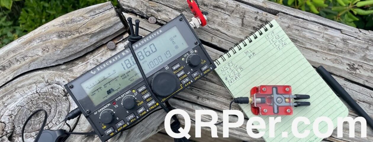
For example, in this video, I feature my venerable Elecraft KX2 kit (see photos above).

But I can take that one out and replace it with either my Elecraft KH1, CFT1, or MTR-3B field kits.

They are all packed in small Pelican cases that easily fit in the center of my backpack.
Weight
 When fully loaded, my backpack isn’t exactly lightweight. Besides all of my radio gear, I’m usually packing a bottle of water too. I haven’t weighed it, but it’s relatively heavy. That’s not an issue for POTA since I’m rarely walking more than 10 minutes (and often just 2 minutes) to find a site to set up.
For SOTA outings or hikes that are an hour or more, I shed any items I know I won’t need. That frees up space for more water and lightens the overall load.
For example, on SOTA hikes I plan to only take my Elecraft KH1 transceiver and a few accessories. That means I can leave behind cable assemblies, extra keys and key base, POTA20 mast, ground spike, and throw line and weight. (The KH1 kit includes a minimalist throw line/weight if needed.) It significantly reduces the pack weight.
In fact, I brought a second, smaller backpack for times when I want to go very minimalist with the KH1 or MTR-3B. Both have fully self-contained field kits in individual Pelican cases. This smaller backpack is perfect when I’m with family—say, spending the day in Vieux Québec visiting museums, shops, restaurants, and one or two urban parks where I can squeeze in activations.
Extras
Note that there are a few extras always in my car that I didn’t include in the video because they typically stay there: my portable table, HT, and a 2-liter water bladder.
 Also, a bedroll that we use for family picnics. All of these items work for both field radio, family picnics, and lounging on the shores of the mighty St-Lawrence.

All of these items get heavy use since our family spends so much time outdoors.
Video
In the video tour of my field radio backpack from this trip to Canada, I take you through each individual item I packed. Below, you’ll find links to each item (when available), in the order they appear in the video.
Click here to view on YouTube.
Gear List
 Note: All Amazon, CW Morse, ABR, Chelegance, Spooltenna, eBay, and Radioddity links are affiliate links that support QRPer.com at no cost to you.
(In order of the video presentation.)
- GoRuck GR1 USA (21L)
- HEROCLIP Carabiner Clip (attached to my backpack)
Outer Pocket, Outside Flap
Top Pocket, Inside Flap
- Nitecore NU25 Headlamp (current model)
- BaMaKeY TP-III Ultra-Compact Twin Paddle, Senrog Bench Block TP-III base, and Tufteln TP-III Magnetic Protective Cover
- Garmin InReach Mini
- GraphGear 0.9mm 1000 Automatic Drafting Pencil
- Rite In The Rain Top Spiral Notebook (small 3×5 size)
- Larabar
- Retractable Key Cable
Lower Pocket, Inside Flap
- ABR Industries 25’ RG-316 cable assembly with three in-line ferrites (Use Coupon Code ABR10QRPER for 10% Discount!)
- OSMO Action Camera with Joby tripod
- Audio Patch Cable
Main Compartment
- Elecraft KX2 Field Kit
- LowePro CS60 Hard Side Case
- Elecraft KX2 with Windcamp X2 Side Rails and Cover
- Elecraft AX1with 3D-printed Bipod (clip and knob by K6ARK and bipod legs by KE8PTX)
- Rite In The Rain Top Spiral Notebook
- KOH-I-NOOR 5219 2mm Lead Holder Pencil
- AD8HK Homebrew End-Fed Random Wire
- Spooltenna 40 Meter End-Fed Half-Wave
- Mini Arborist throw line kit: Tom Bihn Small Travel Tray, Marlow KF1050 Excel 2mm Throwline, and Weaver 8 or 10oz weight
- Helinox Chair Zero
- Helinox Protective Ground Sheet
- Explorer POTA20Carbon Fiber Mast and Adventure Gear Ground Spike
- Elecraft AX3 Package with KE8PTX Clamp and Strap Mounts
- Digital Recorder Kit: Sony Digital Recorder, Pelican 1015 Case, Panasonic ErgoFit Earphones, AAA batteries
- Thermacell Mosquito Backpacker Repeller
and fuel canister in Tom Bihn Travel Stuff Sack Size 2
Interior Zippered Pouch
- Spec-Ops Brand Op Order Pouch
- Tufteln 12V LiPo Battery Pack
- Tufteln Battery Charger 12V Lipo USB-C
- Tufteln USB-C PD Power Supply
- Rite In The Rain Top Spiral Notebook
- GraphGear 0.9mm 1000 Automatic Drafting Pencil
Interior (Ruck Plate) Pouch
Outside of Pack
- Yaesu FT-2D (Current Model is the FT-5DR)
- SignalStick Antenna
- NEMO Moonlander Portable Table (Not Featured in this Video)
- Kleen Kanteen Single Wall Stainless Water Bottle
More to come!

This video didn’t take long to shoot because, as you know, I don’t edit my videos—they are what they are.
Putting together all of the links and video chapters, however, takes a long time. I do plan to make a video of my other, more minimalist backpack and my new Red Oxx Gator EDC bag I’m using for all of my extra supplies.

I’d love to hear your comments about your own field packs—and I especially enjoy your Field Radio Kit posts for our Field Radio Kit Gallery!
Thank you
 Thanks for reading this post—I hope you enjoyed the “What’s in my pack?” video. I certainly enjoyed the process. It was a fun excuse to nerd out about packing!
 Of course, I’d also like to send a special thanks to those of you who have been supporting the site and channel through Patreon, and the Coffee Fund. While not a requirement, as my content will always be free, I really appreciate the support.
Thanks for spending part of your day with me!
Cheers & 72,
Thomas (K4SWL / VY2SW)


