 After the success of my previous day’s activation at Fort Dobbs State Historic Site, I decided to take the Icom IC-703 Plus out for yet another activation.
As I mentioned in the previous post, the IC-703 has not gotten a lot of outdoor time this year because I’ve had issues with the electronic keyer locking up when using the radio with end-fed antennas.
Of course, there are a number of ways to mitigate or radiate the RF that could be coming back to the radio, so at Fort Dobbs, the previous day, I used a simple common mode choke. It seemed to do the trick.
I was curious if using a common mode choke might be the only solution needed to solve this problem, or if I’d need to perform a mod to my IC-703.
I was ready to test the IC-703 again.

I had a fair amount of antenna options in the trunk of my car, so on the way to Tuttle Educational State Forest (on Friday, October 7, 2022), I considered a few options to shake things up a bit.
Since I was feeling comfortable that the common mode choke was taking care of things, I decided to push the limit a bit and deploy an end-fed random wire antenna. I didn’t have any of my mini portable 9:1 random wire antennas in the car (PackTenna, Tufteln, etc.), but I did have another solution: the Chameleon MPAS Lite.
The cool thing about the CHA MPAS Lite is that while it’s primarily designed to be a vertical antenna with counterpoise, it can be reconfigured and deployed a number of ways including as a simple end-fed random wire antenna.
After giving it some thought, I decided it might be fun to deploy it as an inverted V random wire. In fact, here’s a diagram from the MPAS Lite manual of exactly what I planned to do.

I’d be using the MPAS Lite counterpoise as the radiator, so I wouldn’t have the optional second counterpoise as seen in the illustration above. That’s okay, though, because I was feeding the antenna with Chameleon’s 50′ RG-58C/U cable with in-line choke; the shield of the coax would act as the antenna counterpoise.
This is the same coax cable I used the previous day.
Tuttle Educational State Forest (K-4861)

As I drove into Tuttle, I could see that I’d essentially have the entire park to myself. Not a bad thing since it would give me ultimate flexibility finding a choice site.
Setting up
 I found a great picnic table with a short path leading to it. Looking at the canopy overhead, I saw an ideal branch to support the apex of my inverted V.
I grabbed the Chameleon CHA MPAS Lite and attached the counterpoise to the top of the matching unit so it could serve as the radiator.


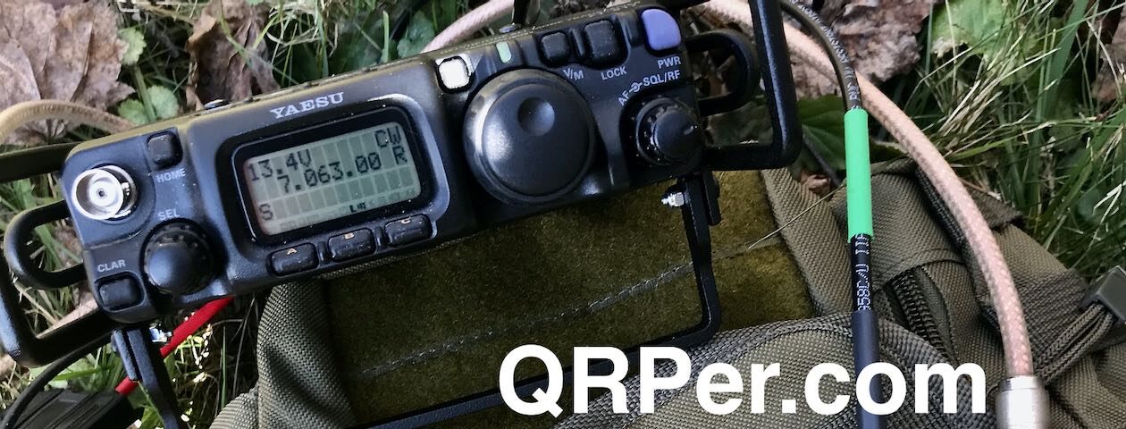
Next, I set up the antenna, prepared the Icom IC-703, then connected the 50′ coax feedline.
I should note here that I give a proper tour of my setup in the activation video below.

Turns out, I was a little too optimistic about this radio and antenna pairing.
I sat down at the radio, got a great match via the internal ATU, and started calling CQ POTA.
This is when I discovered that–sadly–the electronic keying was locking up again. It consistently added extra dits to some of my CW elements.
Argh!
After giving it some thought, I decided that perhaps I could set up the exact same antenna system I’d used the previous day with success at Fort Dobbs.
Plan B: MM0OPX End-Fed Half-Wave

I packed up the Chameleon MPAS Lite and deployed my MM0OPX EFHW in an inverted V configuration using the same branch I’d used with the MPAS Lite.
Again: this was the same antenna/feedline/radio pairing was identical to the one I used successfully the previous day at Fort Dobbs, save the way the coax was laying on the ground.

I started calling CQ POTA and, once again, the ‘703 keyer was locking up–including extra dits I was not sending.
Dang…
I had one more thought: perhaps if I used my CW Morse CNC Machine aluminum paddles, my hand would add a bit of capacitance? I’m not an engineer, but this was very easy to test, so I hooked up the CNC paddles and, unfortunately, there was no change. The keyer continued to lock up.
The only other option I could think of that might have worked would have been to put the IC-703 in hand key mode and use the left paddle as a straight key.
This is what I would have done in order to complete the activation, had I not a secret weapon tucked away in my backpack.
Plan C: Ingrid

I had my new-to-me second Elecraft KX1 “Ingrid” tucked away in my pack. This little rig saved an activation two days prior (read that report here) during its first POTA activation.
Turns out, I would need this little rig to save this activation as well.
I hooked the KX1 up to the MM0OPX EFHW and I was off to the races.
Gear:
- Elecraft KX1 3 bands, ATU, and paddles (a.k.a. Ingrid)
- Pelican 1060 Weatherproof Case (affiliate link)
- Moleskine Cahier Journal (affiliate link)
- MM0OPX QRP EFHW (Contact Colin for Availability)
- Spec-Ops Brand T.H.E. Pack EDC
- Elecraft KXBT2 Li-Ion Battery Pack
- Mini Arborist throw line kit: Tom Bihn Small Travel Tray, Marlow KF1050 Excel 2mm Throwline, and Weaver 8 or 10oz weight
- Rite In The Rain Weatherproof Cover/Pouch (affiliate link)
- GraphGear 0.9mm 1000 Automatic Drafting Pencil (affiliate link)
- Camera: OSMO Action Camera with Joby tripod (affiliate links)
- Sony ICD-FX312 Digital Recorder ($20 thrift store find)
On The Air

I was happy to finally send my CQ POTA with no extra dits!
I started on 40 meters and worked two stations in 8 minutes. I felt like 40 was quite weak, so I QSYed up to the 20 meter band.
Wow…what a difference.
 Twenty meters was hopping.
Within seven minutes, I worked the additional 8 contacts needed to validate my activation.
That was quick!

I continued logging hunters on 20 meters and snagged a total of 18 giving me a total of 20 logged contacts on both bands. I called QRT because it was time to pack up and move on to yet another park that day.
QSO Map
Here’s what this activation looked like when plotted out on a QSO Map. Note that I was running about 3-4 watts.

Activation Video
Here’s my real-time, real-life video of the entire activation. As with all of my videos, I don’t edit out any parts of the on-air activation time. In addition, I have monetization turned off on YouTube, although that doesn’t stop them from inserting ads before and after my videos.
Note that Patreon supporters can watch and even download this video 100% ad-free through Vimeo on my Patreon page:
Click here to view on YouTube.
Time to modify the IC-703!
 This activation made it clear that I need to perform the keyer mod on my IC-703 Plus.
I know that I could deploy an end-fed antenna with a counterpoise system and likely mitigate most of the RF traveling back to the radio on the coax shield, but I’d like my ‘703 to be able to use the same antennas my other radios can. Hopefully this modification can help.
Thank you
 Thank you for joining me on this activation! I’m grateful I decided to record this one because I think it’s important to share field frustrations along with field successes. In a sense, I actually enjoy sorting out issues in the field. I feel like it makes me a more prepared operator.
These things happen–especially if you experiment with the types of antennas and radios you take to the field.
I hope you enjoyed the field report and my activation video as much as I enjoyed creating them.
 Of course, I’d also like to send a special thanks to those of you who have been supporting the site and channel through Patreon and the Coffee Fund. While certainly not a requirement as my content will always be free, I really appreciate the support.
As I mentioned before, the Patreon platform connected to Vimeo make it possible for me to share videos that are not only 100% ad-free, but also downloadable for offline viewing. The Vimeo account also serves as a third backup for my video files.
Thank you so very much!
Cheers & 72,
Thomas (K4SWL)
Very interesting topic for me since I have had a similar issue with my Hendricks PFR3. This great little radio only has 2 keyer memories. Sometimes during a QSO keyer memory #1 transmits spontaneously. I believe this maybe due to common mode current on the feedline. I will try a CMC choke at the rig end of the coax to see if that works. I am also going to check whether Icoms 703 mod can be adapted to the PFR3.
Thomas
With so many portable antennas available today it may be difficult to select the right one for a particular rig or type of operation. After trying many different brands, types and designs resulting in mixed performance, I have settled on one that I think is worthy of note. I use an EFHW that I built from an excellent article by Steve Yates, AA5TB. I deploy the wire in whatever configuration I want, vertical, inverted V or sloper, attach the analyzer and tune it to match, usually with an SWR of 1.2 :1 or less. Steve’s design has always performed better in the field than any of my EFRW or EFHW using transformers of 9:1 or 49:1 ratios and a rigs internal tuner. I have constructed these antennas with parts on hand and have purchased specific parts for construction for less than $30. A good match can be made using the rigs SWR or power meter if an analyzer is not handy. Steve’s article may solve the problems many portable operators may encounter.
I have worked mostly with 2 antenna when doing park events.
40m OCF dipole and End Fed, both on 20ft portable flag pole.
Have not compared at one event, but plan on doing so at our local Nov 19th QRP park event.
I use 20 ft portable flag pole for both, OCFD mounted at balun on the pole and End Fed one end on the pole, balun end at 6 ft.
I have tried my ElectroCraft AX1, it sucks, 7-8 S-unit below the OCF dipole.
One issue with any antenna for POTA, make it so one can get up quickly.
73, ron, n9ee
I often use end fed wires in close proximity of the operating location as well. I have found that installing a snap on ferrite bead on the paddle line near the rig helps.
Another great activation video, Thomas. I guess the “P” in POTA really stands for Persistence. Adapt, improvise and overcome!
Well done.
Hi Thomas,
It looks like you have enable squeeze keying on the ICOM radio. It always added some element after almost every characters you’ve send. The Curtis B usually does that when you are trying to key like with Curtis A.
I really like your videos. I’m active from OKFF areas from WWFF program using KX3 and EFHW antenna. It’s almost impossible to make 44 QSO to have activation valid without spot in the DX cluster network.
Take care and I’m looking for more videos.
73 Petr, OK2CQR
Hi Thomas,
I bought my IC-703 in 2004 and shipped it to Icom Service. They did the keyer mod and driver bias adjustment under warranty. I didn’t have a bench and took this route. Maybe check out the driver bias adj too. Hams were blowing FET transistors with early production runs of the rig.
73 Kevin N2TO
I will definitely check on both. Thanks, Kevin!
I know “Plan C” well.
Plan A: I started POTA thinking of using the LNR “trail friendly” EFHW with my KX3, but that was a great disappointment when I first deployed it at 30’ in VP5. Then I remembered how it was a loser on Field Day 2019, giving way to a home-brew 20/15 wire ground plane.
Plan B: Not prepared to give up on wire, I bought an OCF 40-6 meter dipole. That was much better than the LNR, but nowhere close to the results I get with my Butternut HF9V with elevated radials.
My plan C — implemented on my 5th POTA activation (I’m now at 62 since May of this year) — the PAC-12 (JPC-12) vertical system on AliExpress. I bought the whole kit for about $120, but bought extra mast sections so I could elevate the antenna to 5 ‘ and use 3-4 elevated radials on 20, and 2 on 40.
Blew me away.
I then figured out that a) 20 CW is the best POTA band at this point in the sunspot cycle, and so, b) why not optimize for 20?
I bought a 5.6 meter telescoping whip on AliExpress, raised that 5 feet — and wowsa! I just shorten it for 17, 15 and 10 meters. And even though I don’t have radials for those bands (yet), I work the world. It’s amazing. I can work 2 – even rarely 3 — hunters per minute . It’s rare that I don’t work 2-4 EU stations per 90 minute activation, in addition to 30-80 domestic hunters. 10-15 watts.
I’m leaving for NP2 (St John US Virgins) this weekend. I have a new five-watt 20 meter QCX mini — it seems to be only a few dB below the 15 watts of the KX3 on RBN, and I get darn near every POTA activator I call with it from home. Even bought a beach-umbrella “sand auger” to be able to work under a palm.
The “secret” — if there is one — is to stay away from NVIS antennas (virtually all wire antennas at less than a wavelength above ground) when running low power. Push your RF out at the lowest takeoff angle you can. That’s virtually ALWAYS a vertical with raised radials (4 radials at 4 feet = 64 in or on the ground).
W3PYF