 Many thanks to Allen (N4NN) who writes:
Hello Thomas,
Enjoyed your last video with the QCX-mini as it reminded me of my first portable setup.
Last August, I celebrated my fifth year as a ham and at 74 I’m still able to do some backpacking. This was my first attempt at taking a radio along. The QCX-original was the only model at the time and sold for $49 + shipping. The case is a dollar store pencil box with the radio mounted on stand-offs.

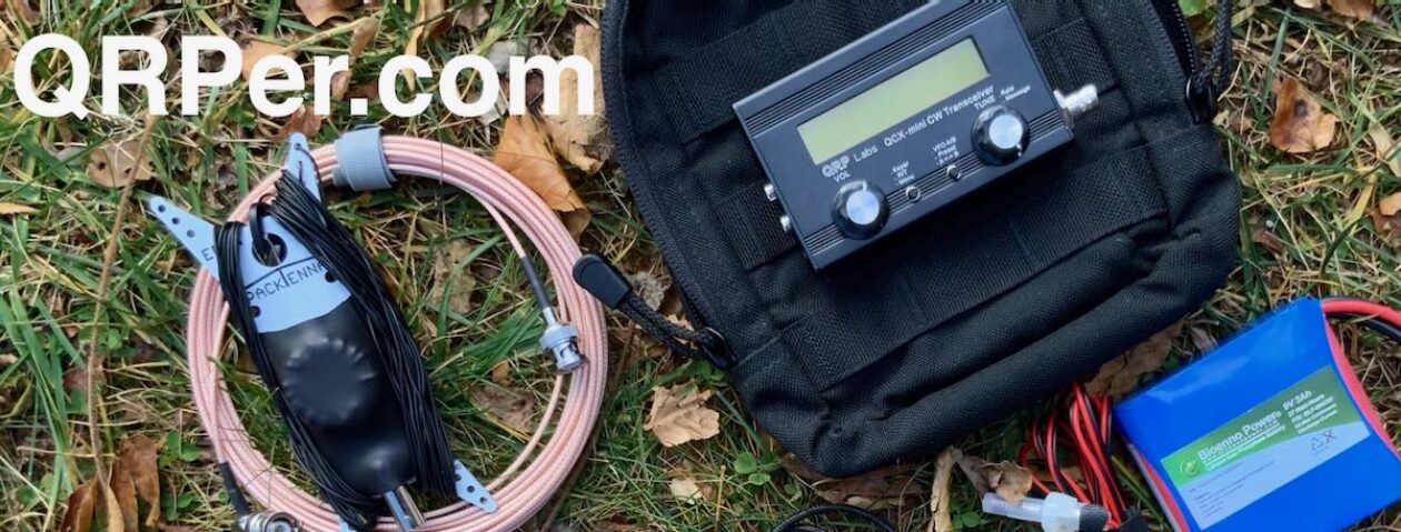
I changed the antenna you see to K6ARK EFHW setup with counterpoise. No coax. I used the on-board key. The throw line was arbor line much like yours and my weight was the tent peg pouch filled with rocks from the camp site. This was my food bag hanging setup. Under $100 for everything.

Before I used it much I discovered POTA from you and purchased a KX2. Haven’t camped much lately but I have activated 70 of Georgia’s 203 parks and having a ball!
[I should note that a] few years back when I made the kit, prices were lower so it may be more difficult to hit that $100 mark. For example, a QCX-mini (no case) runs $57.79 and the QRPGuys EFHW kit is now $30. Adam’s (K6ARK) EFHW kit I changed to is only $20. The “water resistant “ pencil case is still $1! I was more interested in weight rather than cost and as shown the weight is 22.5 ounces.
Thanks Thomas and wish you and yours a Merry Christmas and peace and good health in the coming year.
Allen
72
Allen
N4NN
I love it, Allen! Pure QRP fun on a shoestring budget. Not bad at all! You make a good point here that many kits can be built into a waterproof (or in your case a water resistant) case. I’ve often wanted to do this myself and may very well one day!
Thank you for sharing!


