I really like homebrew radio. I’m also seeing a pattern: I build through the winter and the spring, get rusty at CW, and then spend the summer operating POTA until my ears bleed. So it’s good to be back! Here’s a quick report of a new radio I built and its maiden voyage.
For the past eight months I have worked on what I call the Thunderbird (v2) named after my local state park, Lake Thunderbird. It’s an 8-band (80-10 meters) 5-watt CW transceiver with SSB receive. I emphasized the latter (decent crystal filter and big speaker/audio amplifier) because while I don’t often use a microphone, listening to voice is both comforting and exciting – I love when the VK and ZL stations drift in late at night. It also works as a somewhat competent general coverage receiver for short wave listening. I built it to operate both in the shack and on a picnic table, it unfortunately is a bit heavy because I got greedy and kept adding bands.
I guess I “designed” this radio, but as I discussed before on this site I’m just a guy with no engineering background who learned to solder and read a schematic diagram. But by doing so I could understand and modify the clever circuits from the radios we love and then figure out how to make them play nicely together.
I built the radio using Manhattan construction on copper boards, and then stacked these and fit them into a metal project box with 3D printed front and rear panels. It’s a bit fiddly and messy, but I feel like I’m ready to challenge my family to a game of Operation! The nice thing about stacking the boards is that I can shield the receiver from the transmitter and digital components.
The bottom board houses the band-pass filters, receiver, and audio chain. This was my first attempt at building a superheterodyne receiver so I was a bit nervous (although this video calmed me down). The receiver takes inspiration from John Dillon’s (WA3RNC) TR-35. He uses a clever design to narrow (for CW) and widen (for SBB) the crystal filter. I also cribbed his excellent idea for the LED signal-strength meter. The audio chain was modified from the Elecraft KX1 which includes an AGC circuit. I learned last summer how important AGC is when I was on Vail Pass in Colorado and actually fell out of my chair and groaned in pain when a guy with an amp called me back. I also hand built an NM0S Hi-Per-Mite to switch in when I want a steep 200-Hz filter. This is an awesome circuit that you can buy in kit form.
Like I mentioned, I got greedy and experienced project creep. Honestly, I would have been super happy with 40, 30, and 20 meters, and 17 would be nice. But so would 15, and 10, and even 12 (a band that I only have a handful of contacts on ever). And why not 80 meters? So I modified Steve Weber’s (KD1JV) Tri-Bander relay-switched band-pass filter design to add them all. I also figured out how to build a preamp for the high bands. I built a secondary audio amp to drive a 3-inch 3-watt 8-ohm speaker for annoying my family at night.
The lower board with the receiver, band-pass filter board, and audio chain.
The top board houses the transmitter and the digital components. The transmitter is based on Steve Weber’s design because it’s perfect and is used in some form by many QRP CW rigs. It gives me between 4-6 watts output on all bands. Like with the receiver, I used his design for the low-pass filter board.
The heart of the transceiver is an Arduino/si5351 combination and the Arduino code written by Paul Taylor (VK3HN). Besides doing the heavy lifting of aiding me pull audio out of the ether his code and associated circuits are versatile and clever, including automatic filter switching, CW messages, and both keyer and straight key support.
Although I am mildly terrified of AI, ChatGPT helped me add all kinds of bells and whistles (on my own I’m not a very good programmer) such as RIT, audio filter switching, keyer speed control, and a simple but detailed display that shows the relevant information. The panel controls are all knobs and switches.
The upper board with the transmitter, low-pass filter board, and digital components.
Between the sub-par band conditions as of late, and my neighborhood’s increasingly nightmarish RFI, testing the radio’s real-world performance was difficult. Luckily I have an IC-703 on the bench and it keeps me sane. The Thunderbird isn’t as good but it’s maybe 85% of the way there (when I turn off the DSP and noise blanker on the Icom)? It has been disconcerting when 10-meter FT8 isn’t coming through, but apparently that’s the sun’s fault and not mine. But this radio was built for POTA, so onwards to my park!
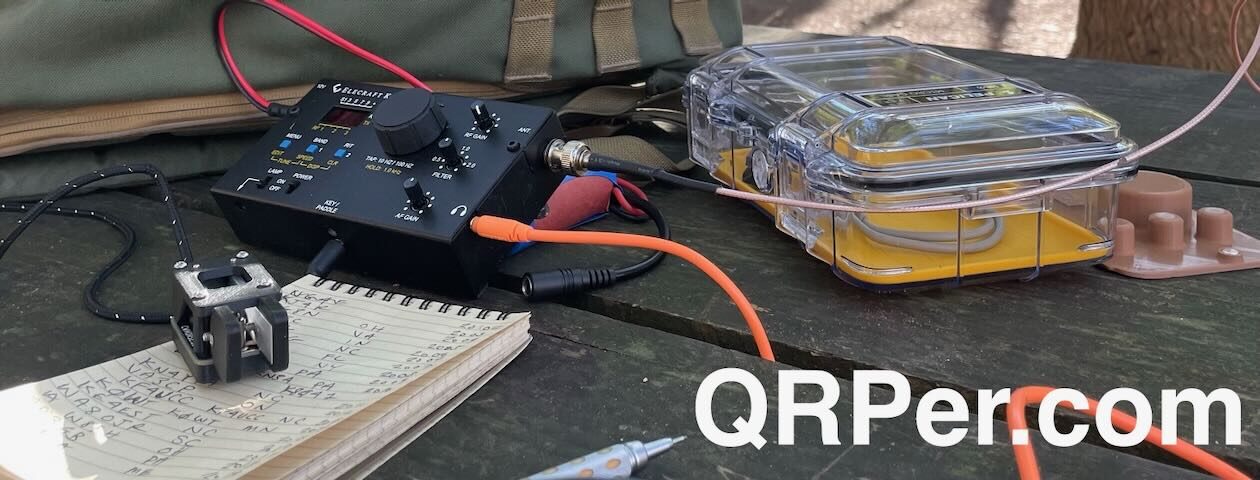
For an activation it was a rush job. I had just finished with the fixing a few loose connections when I realized I had about an hour of time before picking my kid up from camp. So I headed to the park with the radio, my favorite easy-to-deploy antenna[QRPer affiliate link], and my ATU-10 (doubles both as a tuner and check to see if the radio actually works).
There has been a lot of rain here lately so my usual spot was underwater. As I was setting up on the high ground a car drove past me multiple times. I figured I was either in trouble or it was a ham, and fortunately it was the latter. Larry (WA5NTF) and I had a nice chat and he graciously drove across the bay to absolutely clean up on digital. For me, I spent about 30 minutes on 20-meters, got 25 contacts, and then failed on the high bands. This is my first solar-cycle peak: get it in gear, Sun.
A few observations: I really liked the speaker! I was away from others and could use it without invoking ire, and it was freeing. Same with the message function which helped because it wasn’t a day of pileups. I also am so used to an S6 noise level on 20-meter SSB that when I first started the radio I assumed it was broken, so quiet. What a difference being out of the city makes.
But it worked! I have some trips planned for the summer and fall to the Southwest so I can’t wait to lug this box to some weird places. And I’ll hopefully be operating locally quite a bit more. Hope to hear you on the air, hopefully on the high bands!
And a postscript, I’m not going to be a homebrew proselytizer, but if you have an inkling to try something new a great project is the SolderSmoke direct conversion receiver (I started with something similar). On this page there is a link to their active Discord server with friendly people and lots of guides on how to hand build a 40-meter receiver. Paired with a simple transmitter it would make POTA (even more) ridiculously fun.
For the second activation, I wanted to take Vlado to a site I’ve activated numerous times—one of my favorites—that he had yet to visit:
Table Rock State Fish Hatchery (US-8012)
We arrived on-site around 11:00 AM and, no surprise, had the place to ourselves. Honestly, I was hoping we’d see the three dogs that often pop by for a visit, but I believe they were on vacation with everyone else!
We both figured 20 meters would be our bread-and-butter band for this activation. More importantly, our transceiver was a 20-meter monoband (more on that below), so I deployed my new 20-meter end-fed half-wave antenna.
This particular EFHW is built on a transformer by Walter (NE4TN) at TennTennas.
TennTennas 49:1 QRP Transformer
I may have mentioned before that Walter gave me this little 49:1 transformer at Hamvention this year when I met him in person. Walter is one of my top hunters in POTA, and I can often count on hearing his call when I’m on 40 meters.
Walter handed me this little transformer as a thank you, with no obligation to promote it—in fact, he didn’t even tell me where they could be purchased.
But I’m a sucker for home-grown mom-and-pop ham radio businesses, so of course, I’m going to plug it! He sells these on eBay (partnership link) for $39 each as a small side business. Not a bad price for a solid little 49:1!
As I mentioned, I trimmed this one for 20 meters, but I’ll likely make it a linked antenna with 30 and/or 40 meters as well someday.
Vlado’s Homebrew Transceiver
I was also excited that Vlado brought along his homebrew 20-meter QRP transceiver.
I had seen this radio in his shack during various stages of development, but I had never had an opportunity to use it in the field.
I’m not sure if Vlado had used it for a POTA activation yet, in fact.
His little transceiver is super simple but sports proper filtering, an OLED display, and, despite the large battery he connected to it, has modest power requirements.
He built it into an old Kenwood VHF radio chassis he found at a hamfest. I’ve been with Vlado before when he’s hunted for chassis for his various homebrew projects. The OM is always building or repairing something in his shack.
We were really looking forward to putting this little transceiver on the air!
Gear
Note: All Amazon, CW Morse, ABR, Chelegance, eBay, and Radioddity links are affiliate links that support QRPer.com at no cost to you.
My good friend, Vladimir (Vlado) Karamitrov (N3CZ/ZS6MG) is someone who likes to challenge himself. Perhaps this is why he’s such an accomplished DXer and contester.
Recently, at his QTH, he showed me one of his latest projects: a home brewed QRP transceiver. Vlado wasn’t content to simply build his own high-performance transceiver; no, he needed a built-in challenge.
Here is the story of his QRP radio, that he built mostly from junk parts, in his own words:
N3CZ's QRP rig front face
Challenge for all of us ….”Built your own radio”
By N3CZ / ZS6MG, Vladimir Karamitrov, 114 Russet Ln. Asheville, NC 28803 USA
Building your own radio is a challenge on its own. Using it to work DXCC is another challenge, probably less difficult. But combining the two brings a new spark and joy in our hobby. Isn’t ham radio about radios?
The purpose of this article is not to argue the need for building but to give ideas to those who have the time, like a new challenge and open up for ideas of building their own radios.
There are many different aspects to look into this. One is to build a radio from a kit. A search online will provide a list of manufacturers who offer these kits from basic thru intermediate to advanced designs.
The other approach is to build it your self. Yes, from scratch. Well, why not? Remember, time is what is needed most and of course some money and/or spare parts or junk parts. Time is not what I have available a lot, money is always on the agenda but having spare parts and stuff lying around your garage is another good resource.
N3CZ's workbench
So I decided to put something together. No time –means I can’t spend a lot on making this new rig look like a factory made, I have to use dead-bug design techniques and other easy methods to “glue” everything together. Available time is only after work and weekends and that is not much.
What kind a circuit and design to use? This was really the main question, because the answer will dictate what approach to take. First rule is check what parts and components you have available. There is something you have to remember here — when you go to a hamfest always bring some “junk” back home. You never know what you going to need. We all know this rule don’t we? Also don’t forget what your buddies have collected over the years, they will be able to help you with some of the missing parts if you need.
One of my passions is building my own equipment. Starting from antennas, to control boxes to switch them, pre-amps for the low bands and from time to time build a small QRP rig. Other interests are DX and Contesting, so while putting this radio together I cannot wait to hook it up to my antenna. This is where a little patience is required and I had almost none, hi. But I knew, bands are down for now, I have worked almost everything that was there to work, so will do this one little different and try to slow down a bit.
With my projects everything starts with the box. Few boxes I changed until the right one was in my hand. Next was to find a properly sized knob for the VFO. I then realized that it will take little more time to build all the components so I decided to use my $$ budget and get my self a nice DDS VFO. There are few different ones available online and for around $80. I got a nice programmable one with dual VFO’s and memories, with settable IF offset etc. This seemed to be the perfect fit for the project.
Transmitter
I thought I had all I need to start working on this project, but…..I wasn’t really sure about it yet. While looking for the “start” button and to actually take off with this project, I had yet to find that “trigger” that ignites the spark inside me, so I can say to myself, “yes I am ready, let’s just do this.”
You know the feeling – you feel a bit lazy at the beginning until that moment when that spark gets you. It’s like when you have to mow the lawn, and then you think, “no, it can wait another week, don’t feel like doing it now.” Well, I found my spark – it was not in the box, it was in the tuning knob that I got from a colleague also a ham and one who builds little QRP’s. I was actually explaining to him what I was planning to do, but not sure yet of the concept and how to handle certain parts of the circuit. While discussing all of this, he said he had some parts that he would bring for me and see if I could use some. He did not mention about any knobs, but when I saw them I knew I had what I was missing and now it iss the time to start working on this.
Transmitter PA
Now that I have the heart and the body, and the knob, I did some study of a number of different circuits published in ham radio literature including ARRL’s handbook and many online QRP resources. The goal was to build a simple radio easily reproducible, with reasonably good specifications so you can use it daily. Selection of IF frequency was the next and I decided on using 4MHz as I had access to a pile of some computer xtals of 4.032MHz.
Transmitter keying circuit and low pass filter
Junk stock provided the following:
Double balanced mixer SBL-1,
some 2N5109’s, J310 FET’s,
a few IF amps MC1350,
some toroids and
wire
I was ready to take on my own challenge – build it and work 100 countries with it!
Associated pictures with this article represent certain stages of the building process. As you can see I picked up an easy method for putting all together. I liked this approach for a simple reason that I can go step by step, keep adding components and test each stage as I move forward. There was no need for making PCB…who needs a PCB. In the old days, radios were built on a chassis and components hanging in the air and radio worked.
RX/TX antenna relay
On the other hand there was that perfection starring at me and making me feel a bit guilty, but I had no time to waste but hurry and build this radio in the short time I had available to me. Because you know what, the bands will just open up again, and then I had to do my other part – the DXing, hi so I may not be able to get this done.
I actually put the receiver in a working shape in one afternoon. I had the front end bandpass filter , double balanced mixed, post mixer amp, xtal filter, IF stage and audio section. All tested and worked first time. I spend the rest of the evening listening on 20m. Nothing much there but I found few stations up the band. There were few UA0’s as well. I managed to pick them up but signals were tiny. I decided to check my main radio and compare. I see now…signals were stronger, much stronger, S9 + on my TS850. So I checked few things and found few problems with my initial design: I had to amplify the input signal and my LO signal was too low to produce satisfactory mixing with SBL1. I used a J310 FET transistor for my front end pre-amp, and used single NPN transistor to boost the output of the DDS oscillator to appropriate level.
The receiver
I was ready to fire this thing and …wow, what a difference. I could still hear the UA0’s calling CQ and working others, and the signals were just incredible. Next obstacle was the Xtal filter. I had choose computer xtals that were somewhat matched in frequency, but the filter was way too narrow. I started experimenting with the capacitors around it and found a good medium that showed some good response on the signal quality and bandwidth.
Received signals now sounded “almost” like my ‘850. But I wasn’t happy yet. I was missing some “dynamics” in the signal. It was just a plain CW signal and nothing more to it. Next few days I experimented with an AGC circuit and variable bandwidth for the Xtal filter. After number of changes, I came up with a solid audio AGC circuit and S-Meter. That made a whole lot of difference. Everything was still sitting on the bench, loosely connected together and I was listening up and down the band. There were more stations now…hmm the bands must be opening up or something?
Receiver (left) & Transmitter (right)
For the xtals filter I ended up replacing the fixed caps with varicap diodes which I pulled out from an old TV tuner found at one of the local hamfests. You know that feeling when you can actually adjust xtal filter bandwidth. That is what was missing. I spend hours listening and trying to get into motion for my next step. I was simply amazed what I could pick up with the receiver and how I was able to select different signals, some of them very weak.
I went back and forth between my main radio and this little receiver that was sitting in front of me, still in pieces. “Not much difference is it?”–I was thinking to myself. I actually ended up spending hours in this year’s CQ WPX CW contest and only listening on my new receiver. I was able to pick every signal I wanted, even thru some heavy pile ups. It passed the test! Now I wanted to call these all these stations, so it was time for me to start thinking about the transmitter part.
Receiver front end and mixer
This was nother challenge. I tried one circuit and it worked. Straight forward a TX mixer, bandpass filter, couple stages amplification, low pass filter to the antenna. But I could not get the output power I wanted. I was getting something like 1 W barely making it to 2W. I figured out the reason. It was the transistors I used. Each stage must have enough gain to drive the next one. My final transistor was capable of producing an easy 10 watts out, but I was lacking drive power. I checked the complete circuit and components I had available on hand then decided to make few changes. Remember: the goal was to use what was available and not to go and spend any extra money. I ended up adding extra amplification after the TX mixer. Yep! That was it. That is what I was missing. I was now getting an easy 8W out. I couldn’t wait to hook up the antenna. I had no antenna switching circuit yet, so I hooked up my 3 element SteppIR on the little transmitter and used my vertical antenna on the main radio. Nothing easier than this. I was able to hear my transmitted signal and, at the same time, I could listen on frequency. First call and into UR land…559, “not bad,” I though. I then moved up the band and found a French station ending up a QSO, so I called him and worked him too. I got 579 for my signal. This was getting exciting. I ended up working 10 different countries that evening, mostly Europeans.
I spent the next week or so working on the box and figuring out how to implement the mechanical part of this project and get everything together. I tried using the little radio on 2 different bands (20 and 17M) with excellent results. These have been my main bands this year after they stabilized somewhat and we have them open after work until late. This is the perfect time for experimenting.
Receiver bandpass filter
Final touches can be seen on the rest of the pictures displayed here. I actually used this rig in the IARU CW contest for a while as well as in few QSO party’s on 20m, all with great success. The crown of everything was still to come.
It was getting close to the end of ST0R operation and I had them worked with my main station and KW into antenna on every possible band and mode I could hear them, but that one evening I was listening to their easy going pile-up on 20m working NA stations. The pile-up wasn’t that big and I was thinking,
“should I try this little rig and see if maybe somehow they will hear me?” I wasn’t sure this was going to work, but I hooked up my memory keyer and started pushing the button to send my callsign out. I did this for almost 2 hours. Yes, there was nothing else to do, while I was reading a magazine, I just used the preprogrammed call sign and kept sending it over and over.
Top view of N3CZ's QRP transceiver
Then I heard Lynn W4NL working ST0R with his QRP rig…NO WAY! What is he doing differently then me? And I am going crazy and about to give up, but….I was careful enough to check what frequency was W4NL transmitting so I tune up a little higher then he was. At the same time I received email from Lynn saying he worked ST0R QRP! Yes, I know I heard you Lynn…so I pressed few more time on the keyer. Guess what? It took couple more calls and there he was….smiling at me ST0R called me N3CZ 599 BK. There must have been another CZ I thought, so I send my call, then 599 and then my call again. Sure enough he came back with N3CZ TU. That was it! I did it! I just worked ST0R–a new country in a pile-up with my little homemade radio. I had them worked already on 20 CW , so what if it was a dupe? I knew I did it with my little radio and that was good enough for me. This is where I actually stopped and realized that I have accomplished my challenge. At least I have made it to a milestone, a major milestone. At that time I had well over 60 DXCC countries worked with the little radio, and it was barely 2 and a half months since I started working on this project.
I found this encouraging and I would challenge those readers who are thinking about a similar endeavor to not think twice–just do it! Order yourself a kit at least and put it together. The reward cannot be described here or told by anyone. You have to feel it on your own. Put a challenge for yourself. Make a goal to work 10 states maybe or 10 DXCC countries, or 100. It doesn’t really matter. What matters most is that you give this hobby of ours another chance. A chance that makes it different from any other hobby on this beautiful planet we live on. What better can it be than communicating with others over a the vast emptiness of the space around us and bounce few signals now and then of the ionosphere?
“DX RULES” as my good friend Bill N2WB from Florida say.
N3CZ's QRP rig front face
I say “HAM RADIO RULES!” nourish it with everyday ideas, build your own stuff, don’t just buy that new radio and antenna, ready assembled and waiting for you to simply push few buttons and “work that rare DX”. There are many aspects of this hobby and like with anything in life we have to find it on our own. Sometimes we get help from another ham, sometimes a complete stranger to us, but with the same ideas.
Thanks to Dave K4SV, Phil W9IXX, Lynn W4NL and Carl N4AA who insisted on getting this article done [originally for The DX Magazine]. And all the stations who logged N3CZ/QRP. That was me who called you with this little homebuilt-junk parts radio. Drop me a note if you find this interesting and inspiring, because that was my intention anyway. By the way, I am already gathering parts for my next project. This time it really started with a nice box, but we’ll see. I don’t see that spark yet. I will let you know how it goes.
Until then,
73 & CU on the bands.
TU de N3CZ / ZS6MG / Z35C
Vlado
And thank you, Vlado, for sharing this article for QRPer.com readers! To contact Vlado, grab his email from QRZ.com.
If you have a home-brew QRP project that you would like to share with QRPer.com readers, simply contact us or comment!
Connecting an international community through low-power field radio adventures.
Please support QRPer by adding us to your whitelist in your ad blocker. Ads are what helps us stay online. All of our ads are ham radio related--no junk, we promise! Thank you!

 For the past eight months I have worked on what I call the Thunderbird (v2) named after my local state park, Lake Thunderbird. It’s an 8-band (80-10 meters) 5-watt CW transceiver with SSB receive. I emphasized the latter (decent crystal filter and big speaker/audio amplifier) because while I don’t often use a microphone, listening to voice is both comforting and exciting – I love when the VK and ZL stations drift in late at night. It also works as a somewhat competent general coverage receiver for short wave listening. I built it to operate both in the shack and on a picnic table, it unfortunately is a bit heavy because I got greedy and kept adding bands.
 I guess I “designed” this radio, but as I discussed before on this site I’m just a guy with no engineering background who learned to solder and read a schematic diagram. But by doing so I could understand and modify the clever circuits from the radios we love and then figure out how to make them play nicely together.
 The bottom board houses the band-pass filters, receiver, and audio chain. This was my first attempt at building a superheterodyne receiver so I was a bit nervous (although this video calmed me down). The receiver takes inspiration from John Dillon’s (WA3RNC) TR-35. He uses a clever design to narrow (for CW) and widen (for SBB) the crystal filter. I also cribbed his excellent idea for the LED signal-strength meter. The audio chain was modified from the Elecraft KX1 which includes an AGC circuit. I learned last summer how important AGC is when I was on Vail Pass in Colorado and actually fell out of my chair and groaned in pain when a guy with an amp called me back. I also hand built an NM0S Hi-Per-Mite to switch in when I want a steep 200-Hz filter. This is an awesome circuit that you can buy in kit form.

 For an activation it was a rush job. I had just finished with the fixing a few loose connections when I realized I had about an hour of time before picking my kid up from camp. So I headed to the park with the radio, my favorite easy-to-deploy antenna [QRPer affiliate link], and my ATU-10 (doubles both as a tuner and check to see if the radio actually works).
 A few observations: I really liked the speaker! I was away from others and could use it without invoking ire, and it was freeing. Same with the message function which helped because it wasn’t a day of pileups. I also am so used to an S6 noise level on 20-meter SSB that when I first started the radio I assumed it was broken, so quiet. What a difference being out of the city makes.


