 Many thanks to Scott (KK4Z) who writes:
Hello Thomas,
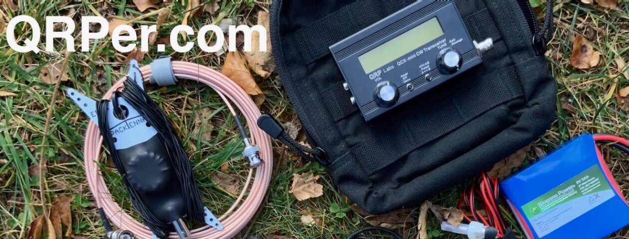
I just finished an antenna project using an antenna I got from you. I call it my K4SWL antenna. I added an UnUn to it:
K4SWL Antenna Plus
Recently, I have had the desire to try my hand at winding toroids. They have always been a mystery to me. Today’s project is winding a toroid for 40-10 meters. My target antenna is one I learned from Thomas, K4SWL. It is a random wire antenna that is 29.5 long with a 17 foot counterpoise. It is a great antenna and works well at park campsites. I either string it up in a tree or I use my 20′ B&M fishing pole.
[Continue reading on KK4Z’s website…]
Scott KK4Z
Thank you for sharing this, Scott. I’ll be the first to admit that I can hardly take credit for the antenna design as it’s been out there for ages, but I do love this simple antenna and it has become an invaluable member of my field antenna arsenal.
I, too, have been planning to build a 9:1 UNUN and pair it with the speaker wire antenna just to make that match a little easier.
Thanks so much for sharing this and your excellent build notes!
Thanks Thomas and Scott.
I already have a 9:1 antenna from Nelson Antennas. It was originally 53′ and intended for home use. I have shortened it to 41′ and I am looking for ways to make it a good portable option for use with my X6100.
I also have the speaker wire antenna that Thomas speaks so highly of and I have had good success with that .
I am thinking about combining the two and seeing what kind of antenna I can come up with. I love experimenting.
Anyone know if a jumper from the coax terminal center post straight to the top of the unun where the antenna wire connects would sufficiently bypass the unun and take it out of the circuit?
W4MKH
https://w4mkh-qrp.com/
I am sure if you connect your center coax directly to the wire it will bypass the balun, the balun would just be hanging from this connection. But then you would be feeding a high impedance with your coax, assume it is 50 Ohms.
The reason for having a balun on an end fed wire antenna is because the feed impedance is high, high voltage and low current and the balun transforms this high impedance down to 50 Ohms.
The speaker wire antenna is more of a dipole fed in the center, just one half is laid on the ground. Most end fed antennas do not have this lower half.
I use with my 65 ft end fed wire a 49:1 balun, does work well, SWR wise and performance wise.
73, ron, n9ee
as for random antenna wire length, my usual “go to” is
https://www.hamuniverse.com/randomwireantennalengths.html
those are tried and true, just, if you want a bit of radiation efficiency, pick a length which is more than 1/4 wave on the lowest frequency and add a counterpoise with a length of at least 0.05 lambda at the same freq, then, to minimize ground losses, place the feedpoint HIGH, and not at ground level (the wire may then slope down)
my 2 cents
Thanks Andrew.
I have been using that page for guidance but I wish he would go into more detail on the counterpoise length.
When we move next month the condo will be upstairs. I’m thinking about opening a window and attaching the feed point then angling the wire down towards the ground. Not sure what to do about the counterpoise length or where to run it.
I guess the best approach is to move then deal with finding a solution that works.
counterpoise… well, give it at least 0.05 lambda at the lowest frequency, more won’t hurt; a combo which I found effective is an antenna wire of 84ft with the feedpoint 29ft from ground, the counterpoise will be a 29ft wire going down to ground (but NOT connected to ground) and two additional 13ft wires connected to it, perpendicular to the antenna wire, running on ground
just to give you an idea, here’s an image
https://postimg.cc/wRXMQ8qZ
showing some pics from a NEC model, the image should make it clear how the antenna is set-up, it also shows the radiation pattern on 40m, the SWR curve at 450Ohm and the impedance curve, so you’ll hopefully have a better idea about what to expect
Thanks Andrew. That helped visualize it.
I understand how the antenna wire and counterpoise are set up but how are the two 13′ wires on the ground connected?
well, the main antenna wire goes to the 9:1 UnUn “+” connector, the vertical counterpoise (insulated !) wire to the UnUn “-” connector and then down to ground there it connects with the two other wires but neither the counterpoise nor the two other wires are connected to ground
Hope it’s clear now, if not… I’m here