
While I tend to use small, field-portable transceivers on many of my Parks On The Air (POTA) activations, I also love using tabletop transceivers when I have a picnic table available or decide to use my portable table. Tabletop radios often provide more power output when needed and better audio from their built-in speakers.
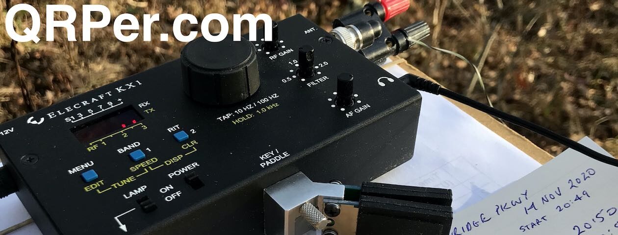
Although I have an Icom IC-756 Pro transceiver, and an Elecraft KXPA100 amplifier that I can pair with my KX2 and KX3 (or any QRP transceiver for that matter), my favorite tabletop fiel;d radio at present is the Mission RGO One 50 watt transceiver.
If you’re not familiar with the Mission RGO One, I’d encourage you to read my comprehensive review over on the SWLing Post.
In short: it’s a brilliant, simple, tabletop transceiver that’s very happy in the field and a pleasure to operate. My RGO One has the optional built-in antenna tuner (ATU). The rig designer is allowing me to keep this unit on extended loan as I help him evaluate and test updates and upgrades.
While I’ve used the RGO One on numerous POTA activations, I don’t believe I’ve ever made a video of it in use, so I decided to change that last week with another one of my real-time, real-life, unedited (lengthy!) videos of this activation (see video below).
Lake Norman State Park (K-2740)

As I’ve mentioned before, I love activating Lake Norman State Park because it has numerous spots for setting up my gear. While I actually prefer activations that require a bit of hiking, it’s nice from time-to-time to activate a state park that has so many widely-spaced picnic tables under tall trees. That, and my right ankle is still healing after I twisted it in December, so I’m avoiding any proper trail hiking until it is better.
I made this activation of K-2740 on January 4, 2021.
Gear:
- Mission RGO One
- Chameleon Emcomm III Portable random wire antenna
- CW Morse “Pocket Paddle”
- Red Oxx C-Ruck
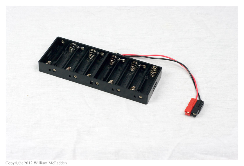
- Bioenno 15 aH LiFePo Battery (Model BLF-1215A)
- Ham Radio Workbench DC Distribution Panel
- Arborist throw line
On the Air

This was my first activation of 2021!
Since I have Internet access at Lake Norman, I can check out the POTA spots page on my phone or tablet and self-spot as well as see spots of other activators.
When I have Internet coverage like this–and I’m not pressed for time–I try to work as many Park-To-Park contacts as I can before I start calling CQ POTA myself.
As I mention in the video, one of my 2021 goals is to obtain a valid activation of each park with only five watts or less. This means that each time I start an activation, at least my first ten stations logged will be with a max of five watts of power. I would actually make the goal for all of my 2021 activations to be 100% QRP, but I evaluate gear regularly and part of that process is to push wattage limits so it’s simply not realistic.
This isn’t actually a crazy goal because a number of my transceivers max out at five watts or less, and I know it won’t be an impediment as I activate parks in CW.
In SSB, though? It makes it a bit more challenging, but certainly not impossible and I’m always up for a challenge!
So I started this activation by trying to work a few Park-To-Park contacts but first cranked the RGO One power down to five watts. Trying to be heard over other hunters in SSB was difficult, but CW was much easier.

After working a few P2P stations, I started calling CQ on the 40 meter band in SSB. I worked about four stations, then switched to CW and worked seven more on 40 meters.
Since I’d snagged my ten contacts for a valid activation, I moved up to 20 meters phone (SSB), cranked up the power to over 40 watts, and started calling CQ POTA and racked up an additional 11 contacts for a total of 26 contacts logged at this activation.
Here’s my QSOmap:

Note that I left the callsign labels off the map this time to make it a little easier to see the geo location of the stations I worked.
Real-Time Video
I made a video of the entire activation and posted it on my YouTube channel. As with my other videos, there are no edits and no ads. It’s all real-time and includes my many goof-ups! But hey–mistakes are all a part of a real activation!
Again, if you’d like to know more about the Mission RGO One, you might check out my review on the SWLing Post.
Feel free to comment with your thoughts or questions and thank you for reading QRPer.com!


