An easily accessible, multi-function button on the IC-705’s “back rim” gives a great improvement over the stock noise reduction. (ICOM, with all your resources, why can’t you design a DSP NR circuit that works as well as BHI’s? )
I admit it! I’m in love with BHI Ltd.’s DSP noise reduction accessories. I’ve owned most of their popular models like the DSP Desktop Speaker, and have installed BHI low-level audio modules in six different receivers and transceivers.
How is it that an audio-based DSP noise reduction accessory can be so effective? Only BHI knows, but they clearly have top-notch algorithms that rival the best of noise reduction circuits in contemporary Yaesu transceivers. (Personal bias alert: I find Yaesu’s approach to noise reduction (“DNR” in Yaesu-speak) to be quite superior to ICOM’s, and this is what got me thinking about improving the transceiver with an internal BHI NEDSP1901-KBD module in the first place.)
The noise reduction feature in the IC-705 and its IC-7300 base station counterpart is merely “OK” in my opinion, but the addition of BHI’s NR makes a significant difference in S/N and intelligibility of signals. It’s simple enough to use an external BHI product and connect it to your rig’s speaker or headphone’s audio path, but it adds wiring and complexity. The ICOM IC-705 modification described in this article is a neat, clean, internal solution needing no external wiring or power supply.
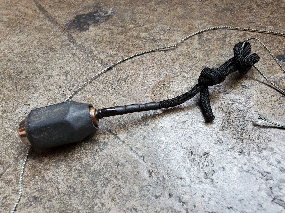
I discovered something you might have an interest in for your wire antenna deployment. Years ago when I was a building contractor, we used chalk line for floor layout. It has a very high tensile strength and is very light weight. After reflecting on this, I recently bought a 100’ spool of braided 1 millimeter chalk line and used it for a field deployment. I attached my “throw weight” to it and easily launched it about 60’ into a tree. You can see it in the attached photo holding my homebrew EFHW to my Jeep.
The magnet wire was scavenged from a HUGE transformer from a neighbor’s discarded light fixture.
Lug Nut Throw Weight: left hand threaded from a 1966 Plymouth Fury
I did the new installation for him and he gave me the old one. I promptly disassembled it and collected miles of 14 and 20 gauge magnet wire ?!
I haven’t added the capacitor to this antenna yet because it is sufficiently resonant and broadbanded on 40, 20, 15, and 10 Meters. I did some testing with the capacitors though on my previous build which was the PVC tube EFHW transformer. I believe I may have sent you a photo of that in a previous message. It too was resonant in the same places, but adding the capacitor smoothed and widened the acceptable SWR range.
The attached photos are my complete antenna assembly: matching transformer (49:1), 65.5’ speaker wire, 100’ braided 1MM chalk line, and throw weight (epoxy filled lug nut with short paracord pigtail).
Compact and lightweight.
Dan/ KQ8Q
I love this, Dan! I also like how self-contained and compact it is. What a professional job, too, with heat shrink, proper connection points and tie-offs.
Brilliant work!
Do you have an antenna or radio project you’d like to share on QRPer.com? Contact me!
Like many I’ve taken the plunge on an Icom IC-705. Even though I sold off an old Yaesu 817 to finance part of it, it still cost a very pretty penny and I didn’t want to shell out more for a tilt stand or bail.
Especially at the rather extravagant prices they’re going for now. $30, $40? No thank you. (Really, the radio, at $1300, should have come with one in the box, but why beat that dead horse – it is what it is.)
In any case, I looked around the house for something to DIY one with. I found a couple of metal angle brackets, screws that fit the mounting holes, and some tiny rubber bumpers to shield from nicking up the radio’s plastic case. Voila! Instant tilt stand. See pics:
And just the right angle too. My plan is to plastic-dip the brackets so I can get rid of the bumpers as well as not nick up any softer surface the radio sits on.
IC-705 Bluetooth Question
Meanwhile, a question for you and other owners of this radio.
What’s up with the Bluetooth function? I have three bluetooth speakers and a small audio amp with built in BT, and I can’t get audio to play through them. The unit sees the accessories and connects. But no sound. I’d updated the firmware to 1.24, just in case they might have addressed any issue. Still no joy.
That being said, I can control the radio via BT with android apps, etc, but no audio. A very disappointing development for such an expensive radio.
Oh well. The good with the bad and all that…
Joe Patti (KD2QBK)
Thank you for sharing this, Joe! That’s a very clever and simple solution for the IC-705 stand.
As for the Bluetooth functionality, I’ve yet to use it. Hopefully, someone here can chime in and comment with advice!
Many thanks to Mark Hirst, who shares the following guest post:
Pick and Pluck Foam
The old adage of ‘measure twice and cut once’ is very apt when using pick and pluck foam. The inserts are not cheap and mistakes are hard to rectify.
Whether you are preparing a large case with several items in a shared insert, or focussing around a single item, planning the layout is key.
Item weight is also a factor to consider, as this will affect decisions on wall thickness between items and the case.
Finally, how hostile is the environment likely to be? Is the case going in your backpack or car where you’re in careful control, or is going to be subject to careless handling by others?
Planning the layout
Once you’ve settled on a case size and how much padding you need, a non-destructive way of planning the layout is to use cocktail sticks.
These can be inserted into the corners of the foam segments to trace the outline of the radio and any items such as controls and ports that may extend from the body.
Since the size of the segments is in fixed increments, matching the exact dimensions of the radio is down to pure luck. I would go for a slight squeeze on the radio body if feasible to make sure it’s always in contact with the foam, but give some breathing room around the controls and ports.
The example below is a case I use for backpack transport. It has rather thin but adequate side walls for that purpose. I prioritised wall thickness facing the front and back of the radio, and also on the side opposite the carry handle. Note how the foam comes right up against the body of the radio, but leaves the front controls with some clearance.
Outlining using cocktail sticks
This has the benefit of keeping any sudden shocks away from the controls, and also reduces the number of places where foam is subject to tearing and compression when the radio is inserted and removed.
The completed insert
Separating the foam
The best place to start is along the planned route of a long side wall. Use your thumbs to separate the surface of two segments on one side from two segments on the other.
Once the surface tear has got going, you should be able push a finger down between the four segments, extending the tear till it reaches the bottom of the foam. At this point, you have a cut all the way through.
Separating the foam
Now you can peel the foam apart at the upper surface in each direction, using your forefinger to again push down between the segments to complete the separation down to the lower surface.
Work carefully around the cutouts and protrusions accommodating the controls. The protrusions are potential weak points at this stage, so be sure to proceed slowly.
If you need to practice, you can always start by separating segments deep within the section that will be removed till you get the hang of it.
Reinforcement
While pick and pluck means you don’t need special tools or templates to cut the foam, the remaining material in your insert is inherently weaker than a solid structure.
The solution I’ve used is to fill the residual cuts with a solvent free adhesive. Solvent free adhesives are often aimed at children for safety reasons, and while there are solvent based adhesives for foam, the one I used dries clear with a resilient flexible bond that is stronger than the foam itself.
I run a finger gently along the exposed walls, edges, and around the protrusions. This makes the potential weak points and stress areas immediately apparent as segments naturally separate along the pick and pluck cuts.
Armed with a tube of adhesive and a finger (usually a thumb), you can gently open the weak point and then run the nozzle of the tube down the cut, dispensing generous amounts of adhesive as you go. The two sections of foam close up as the nozzle passes by, with the adhesive soaking into both sides. As long as you don’t go overboard, the adhesive will stay within the join and you won’t have to wipe away any excess.
Reinforcing corners
Side walls are not subject to the same stress as protrusions, but you will probably still spot sections with deeper cuts that need attention, and you will definitely want to reinforce the corners.
Reinforcing sidewalls
I’ve allowed at least a day to be sure the adhesive has set. It’s worth going over the insert again to see if you missed anything the first time round.
The Adhesive
The Bostik solvent free adhesive resembles runny white toothpaste when dispensed from the tube, but dries clear when set.
Inevitably, when I tried to find more of it recently, I discovered that the easily recognisable colour and branding had made way to a confusingly generic scheme shared across a variety of different adhesive types from the manufacturer.
I found this old listing for Bostik 80518 on Amazon UK, and another here on Amazon US. Based on the product number, a modern equivalent seems to be here.
I’m sure there’s nothing unique about this particular product, other than I’ve found it to be foam friendly over the years. Aside from being solvent free, its ability to seep into the foam is a key asset.
Since the first step of creating an insert leaves you with a potentially discardable piece of foam anyway, you have plenty of raw material to experiment with if in doubt.
Additional Reinforcement
Even if you have been generous with the side walls of your foam insert, a heavy radio might demand some additional work to ensure the longevity of the foam.
While the example case shown above worked OK to start with, I noticed that the floor of the case and the side wall facing the back of the radio were taking a beating.
The problem was caused by the feet of the radio, cooling fins, power and antenna connectors. During transport, these were pushing into the foam with the full weight of the radio behind them. Subject to such concentrated point forces, I could see that the foam wasn’t going to last.
Using very thin and very cheap flexible plastic cutting boards from my local food market, I cut out panels which spread the point compression across a much wider area.
Additional Reinforcement
Now when I put the case into a backpack, I ensure that the radio is sitting on its tail with the cooling fins against the rear panel.
Conclusion
While it’s possible to create ad-hoc transport solutions for radios, there’s nothing quite as satisfying as a sturdy padded case that is made to measure. The cases are forever, but the foam needs care and attention, so I hope these tips help you build a lasting solution for safely transporting your pride and joy.
Andy’s article caused me (yes, I blame him) to wax nostalgic about the popular FT-817 transceiver. You see, I owned one of the first production models of the FT-817 in 2001 when I lived in the UK.
At the time, there was nothing like it on the market: a very portable and efficient HF, VHF, UHF, multi-mode general coverage QRP transceiver…all for $670 US.
In 2001? Yeah, Yaesu knocked it out of the ballpark!
In fact, they knocked it out of the ballpark so hard, the radio is still in production two decades later and in demand under the model FT-818.
I sold my FT-817 in 2008 to raise funds for the purchase of an Elecraft KX1, if memory serves. My reasoning? The one thing I disliked about my FT-817 was its tiny front-facing display. When combined with the embedded menus and lack of controls, it could get frustrating at home and in the field.
I mentioned in a previous post that I purchased a used FT-817ND from my buddy, Don, in October, 2020. I do blame Andy for this purchase. Indeed, I hereby declare him an FT-817 enabler!
FT-817 Buddy board
When I told Andy about my ‘817ND purchase, he asked if I’d like to help him test the FT-817 Buddy board versions. How could I refuse?
Andy sent me a prototype of his Version 2 Buddy board which arrived in late November. I had to source out a few bits (an Arduino board, Nokia display, and multi-conductor CAT cable). Andy kindly pre-populated all of the SMD components so I only needed to solder the Arduino board and configure/solder the cable. I did take a lot of care preparing and soldering the cable, making sure there was no unintentional short between the voltage and ground conductors.
Overall, I found the construction and programming pretty straight-forward. It helped that Andy did a remote session with me during the programming process (thanks, OM!). Andy is doing an amazing job with the documentation.
I do love how the board makes it easier to read the frequency and have direct access to important functions without digging through embedded menus. While there’s nothing stopping you from changing the program to suit you, Andy’s done a brilliant job with this since he’s an experienced FT-817 user.
The Nokia display is very well backlit, high contrast, and easy very to read.
“Resistance is futile”
I mentioned on Twitter that, with the backlight on, the FT-817 Buddy makes my ‘817ND look like it was recently assimilated by The Borg.
Don’t tell any Star Trek captains, but I’m good with that.
Andy has a rev3 board in the works and it sports something that will be a game-changer for me in the field: K1EL’s keyer chip!
Of course, we’ll keep you updated here as well. Many thanks to Andy for taking this project to the next level. No doubt a lot of FT-817 users will benefit from this brilliant project!
Many thanks to Curt (WU3U) who recently contacted me and mentioned he had built an IC-705 control interface for his Elecraft T1 ATU. This is a homebrew project based on others’ work and uses the FT-817 control port on the side of the T1 tuner.
I asked Curt if he could share a little more about his tuner to post here on QRPer:
Hi Thomas, I can’t take credit for the interface, as a guy in Japan designed it. When I built mine the entire instructions and notes for code for the PIC controller were in Japanese. I used Google translate to translate all of the information and I was able to successfully program the PIC chip and build the circuit. He has since released the details and code in English.
There are two designs: one with an on/off switch, and a newer version without an on/off switch that has auto power save. Both circuits are the same but the software for the PIC chip is different. If you build the one without the on/off switch there is a very specific sequence of connecting and disconnecting the device and it’s my opinion that the one with the on/off switch is the version that makes more sense to build. It shouldn’t matter which order you connect everything up and you simply throw the on/off switch to turn the device on and off.
Building the interface takes an understanding of a fairly simple electronic schematic and acquiring the parts. You also have to have a PIC programmer and the software to write his .hex file into the PIC controller chip.
The parts for the interface are all very common parts. The resistors are standard values. My build cost me about $30 in parts but I had to buy many of them in bulk from Amazon like the enclosures, switches and 3.5mm jacks and circuit boards to name a few. Individually the parts were $30 but my bulk order cost me much more. I also had to buy a PIC programmer for $25 and figure out what software I needed to download to program the PIC chip with the author’s code. It takes an experienced builder about two hours to build the device but it’s not out of the realm of a semi-novice as long as they can get the PIC chip programmed.
Here is his newer version with the same circuit design eliminating the on/off switch by using a different PIC program allowing the interface to have auto power shutdown (low power standby) but there is a specific order for connecting and disconnecting the interface. With this version there is still drain on the battery but the designer thinks that drain is less than the normal self discharge of the battery. I feel that any discharge combined with the self discharge of the battery will be more discharge than using the design with the on/off switch. https://amateur-radio.cocolog-nifty.com/blog/2020/11/post-591d17.html
Video
I think this is a brilliant project and certainly one worth considering for those of us who already own an Elecraft T1 ATU and would like full control from the IC-705.
Many thanks to Steve (KZ4TN) who shares the following guest post:
DC30B QRP Transceiver Project
by Steve Allen, KZ4TN
I wanted to build a lightweight backpackable transceiver I could take hiking and camping. I chose the 30 meter band as it is specific to CW and the digital modes. I am also in the process of building Dave Benson’s (K1SWL) Phaser Digital Mode QRP Transceiver kit for the 30 meter band. Also, a 30 meter antenna is a bit smaller than one for 40 meters and the band is open most anytime of the day.
I sourced the DC30B transceiver kit, designed by Steve Weber KD1JV, from Pacific Antennas, http://www.qrpkits.com. It appears that they are now (10-11-20) only offering the kit for the 40 meter band. The following information can be used for the assembly of most any kit that lacks an enclosure.
Lately I have been finding extruded aluminum enclosures on Amazon.com and eBay.com. They come in many sizes and configurations. I like to use the versions with the split case which allows you to access the internal enclosure with the front and rear panels attached to the lower half of the enclosure. Most of these enclosures have a slot cut into the sides that allow a PCB to slide into the slots keeping it above the bottom of the enclosure without having to use standoffs. The one requirement for assembly is that the PCB needs to be attached to either the front or rear panel to hold it in place.
As the enclosure is anodized, I didn’t want to rely on the enclosure for common ground. I used a piece of copper clad board that I cut to fit the slot width of the enclosure and attached it to the back panel. I was then able to mount the transceiver PCB to the copper clad board with standoffs. This basic platform of the enclosure with the copper clad PCB provides a good foundation for any number of projects. All you have to do is mount the wired PCB on the board, install the components on the front and rear panel, then wire it up.
I wanted to have the choice of a few frequencies to operate on so I searched eBay for 30 meter crystals and found a source for 4 different popular frequencies. I installed a rotary switch on the front panel and added a small auxiliary PCB with two, 4 pin machined IC sockets. This allowed me to plug the crystals into the sockets. I wired the bottom of the socket PCB first using wire pairs stripped from computer ribbon cable leaving extra length. I marked the wires with dots to indicate which sockets each wire pair went to so I could solder them onto the rotary switch in the correct order. It was tight but I always work with optical magnification so I can see exactly what I’m doing. I have used this crystal switching method in the past with good success.
The rest of the assembly was straight forward. I find that most kits are well designed and documented, and if you take your time and follow the directions carefully all should go well. The two most common speed bumps seem to be soldering in the wrong component or bad soldering technique. I double check all component values and placements prior to soldering, and I always use optical magnification while working. I inspect each solder joint and look for good flow through in the plated through holes, and make sure there are no solder bridges.
The finished product. I bought a Dymo label maker and it works very well for projects like this. I love using these enclosures and they are a leap forward from the old folded aluminum clam shells I used in the past. I could stand on this without causing any damage. Power out is 1-3 watts depending on the DC power in. The receiver is sensitive and the ability to choose from four frequencies is a real plus.
73 de KZ4TN
Steve Allen
Elizabethton, TN
Wow, Steve! What a top-shelf job on this build! I’ll have to look for those aluminum enclosures as well. Beautiful little rig you’ve made there and I think it’s fantastic you’ve a few crystal frequency options! Thank you for sharing!
Many thanks to Alex (W3AVP) who shares this photos of his homemade cootie/sideswiper originally posted on the POTA Faxcebook page. Alex notes:
I didn’t want to lug my Begali key to the parks so I made my own using the plans from KA8VIT. Worked great! I had a little QRP key but my fat fingers would make so many mistakes. The DIY aspect of this hobby is extremely entertaining!
And I bet your “cootie” serves you well in the field! I love the simple design and the fact it even has an adjustable action. At the end of the day, keys are merely switches so are perfect for homebrewing!
If you have a sideswiper/cootie or any other key you’ve built and would like to share it here on QRPer, contact me (K4SWL at QRPer.com).
Many thanks toPete (WB9FLW), who shares the following:
Don’t know if you are familiar with this project, a full blown 5 watt HF SDR Transceiver for less than $300!
No sound cards, DUC/DDC architecture.
Here’s the project description by Steve Haynal via YouTube:
The Hermes-Lite is a low-cost direct down/up conversion software defined amateur radio HF transceiver based on a broadband modem chip and the Hermes SDR project. It is entirely open source and open hardware, including the tools used for design and fabrication files. Over 100 Hermes-Lite 2.0 units have been successfully built.
The FOSSi Foundation is proud to announce Latch-Up, a conference dedicated to free and open source silicon to be held over the weekend of May 4th and 5th in Portland, Oregon, USA. Latch-Up: a weekend of presentations and networking for the open source digital design community, much like its European sister conference ORConf. Produced by NDV.
This is a simple and experimental modification that transforms a QCX into a (Class-E driven) SSB transceiver. It can be used to make QRP SSB contacts, or (in combination with a PC) used for the digital modes such as FT8. It can be fully-continuous tuned through bands 160m-10m in the LSB/USB-modes with a 2400Hz bandwidth has up to 5W PEP SSB output and features a software-based full Break-In VOX for fast RX/TX switching in voice and digital operations.
The SSB transmit-stage is implemented completely in a digital and software-based manner: at the heart the ATMEGA328P is sampling the input-audio and reconstructing a SSB-signal by controlling the SI5351 PLL phase (through tiny frequency changes over 800kbit/s I2C) and controlling the PA Power (through PWM on the key-shaping circuit). In this way a highly power-efficient class-E driven SSB-signal can be realized; a PWM driven class-E design keeps the SSB transceiver simple, tiny, cool, power-efficient and low-cost (ie. no need for power-inefficient and complex linear amplifier with bulky heat-sink as often is seen in SSB transceivers).
An Open Source Arduino sketch is used as the basis for the firmware, the hardware modification bypasses the QCX CW filter and adds a microphone input in-place of the DVM-circuit; the mod is easy to apply and consist of four wire and four component changes and after applying the transceiver remains compatible with the original QCX (CW) firmware.
This experiment is created to try out what can be done with minimal hardware; a simple ATMEGA processor, a QCX and a software-based SSB processing approach. It would be nice to add more features to the sketch, and try out if the QCX design can be further simplified e.g. by implementing parts of the receiver stage in software. Feel free to experiment with this sketch, let me know your thoughts or contribute here: https://github.com/threeme3/QCX-SSB There is a forum discussion on the topic here: QRPLabs Forum
QRP radios, product announcements, reviews, news and more. Low power amateur radio fun!
Please support QRPer by adding us to your whitelist in your ad blocker. Ads are what helps us stay online. All of our ads are ham radio related--no junk, we promise! Thank you!


 There are two designs: one with an on/off switch, and a newer version without an on/off switch that has auto power save. Both circuits are the same but the software for the PIC chip is different. If you build the one without the on/off switch there is a very specific sequence of connecting and disconnecting the device and it’s my opinion that the one with the on/off switch is the version that makes more sense to build. It shouldn’t matter which order you connect everything up and you simply throw the on/off switch to turn the device on and off.


